
|
 11-19-09, 08:05 PM
|
#1 |
|
Lex Parsimoniae

Join Date: Feb 2009
Location: Woburn, MA
Posts: 4,918
Thanks: 114
Thanked 250 Times in 230 Posts
|
I was reading about the 'Electric expansion valve' here,
Electric Expansion Valve Control - Feature Articles - Extra Edition - Air Conditioning, Heating & Refrigeration NEWS How they help maintain a "constant head pressure", when I remembered seeing one on the diagram of my new Sanyo mini-split.. It's down on the lower right side. Looks like it might be a Motor controlled valve.? 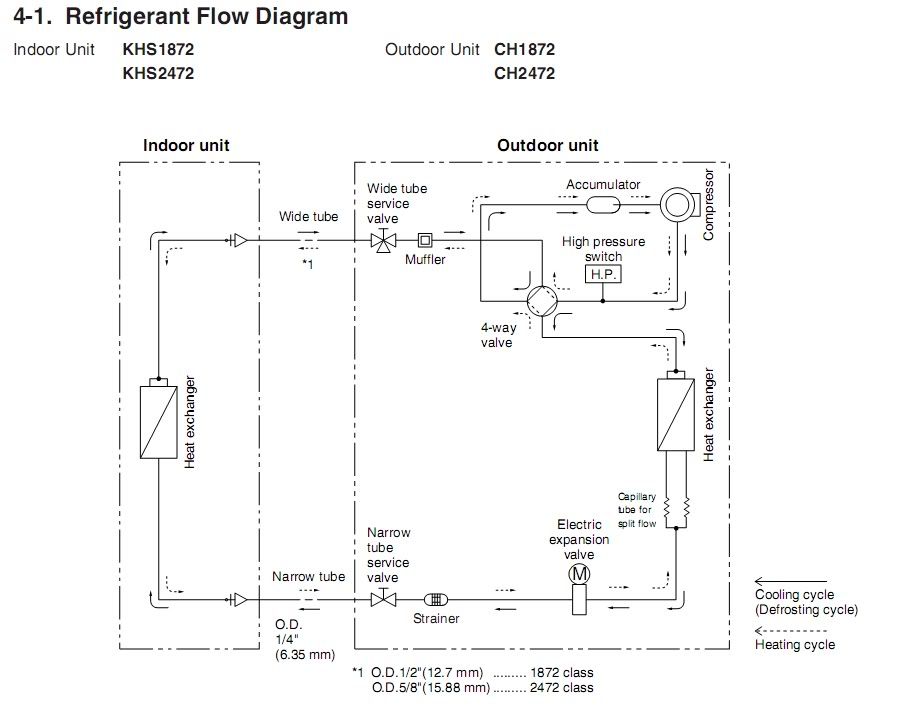 Anyways, I noticed a connection on the block diagram called, MVO. Lower right. 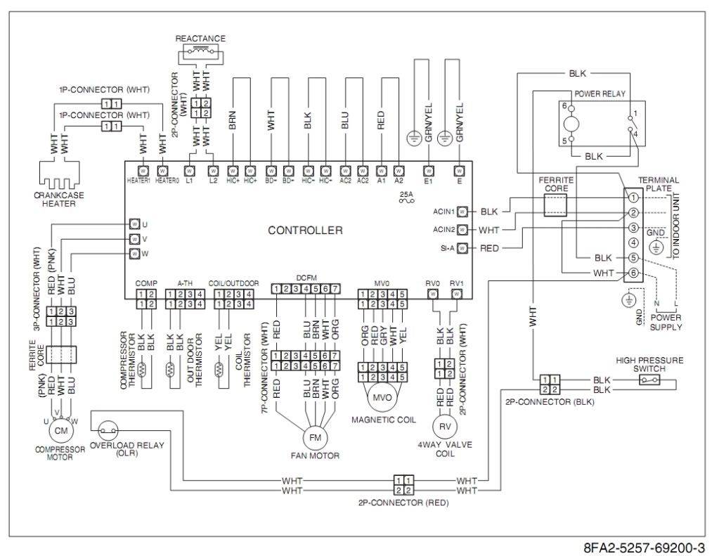 Magnetic Coil?? I never understood what that MVO was.. Is it the 'Electric expansion valve' control?? The other mystery is "Reactance" upper left side. Is that a pickup coil for a spinning magnet on a motor? For speed control feedback? |

|

|
|
11-19-09, 09:28 PM
|
#2 |
|
Supreme EcoRenovator

Join Date: Oct 2008
Location: Austin, TX
Posts: 1,154
Thanks: 14
Thanked 257 Times in 241 Posts
|
It looks like a 5 wire stepper motor to me. But that's just a guess. It could also be a linear solenoid with position feedback.
the function of the electronic expansion valve - Refrigeration-Engineer.com forums LEV'S and EEV's - Refrigeration-Engineer.com forums
__________________
To my surprise, shortly after Naomi Wu gave me a bit of fame for making good use of solar power, Allie Moore got really jealous of her... |
|
|
|
|
11-23-09, 09:18 AM
|
#3 |
|
Supreme EcoRenovator
Join Date: Oct 2008
Location: Austin, TX
Posts: 1,154
Thanks: 14
Thanked 257 Times in 241 Posts
|
Just a wild guess but maybe the "reactance" thing is a power inductor for a boost converter just like in the Prius inverter. If it has thick wires, that's probably it.
__________________
To my surprise, shortly after Naomi Wu gave me a bit of fame for making good use of solar power, Allie Moore got really jealous of her... |
|
|
|
|
11-23-09, 09:33 AM
|
#4 | |
|
Lex Parsimoniae
Join Date: Feb 2009
Location: Woburn, MA
Posts: 4,918
Thanks: 114
Thanked 250 Times in 230 Posts
|
Quote:
Or maybe the AC-to-DC circuitry needed an inductor that was too big and heavy to mount on a small PCB.?. I've seen more than a few heavy transformers get ripped off of their PCBs during shipping. One time, I unpacked about a dozen large switchers made in Mexico. About 10 of them had a free floating 5 pound transformer, crashing around inside. The PCBs were not made out of G10, but some cheapo beige fiberboard. The nuts & bolts popped nice holes in the boards. |
|
|
|
|
|
11-23-09, 05:02 PM
|
#5 |
|
Supreme EcoRenovator
Join Date: Oct 2008
Location: Austin, TX
Posts: 1,154
Thanks: 14
Thanked 257 Times in 241 Posts
|
I don't think an A/C would need such a large inductor unless it had a boost converter or a current mode inverter.
__________________
To my surprise, shortly after Naomi Wu gave me a bit of fame for making good use of solar power, Allie Moore got really jealous of her... |
|
|
|
|
11-29-09, 08:39 PM
|
#6 |
|
Supreme EcoRenovator
Join Date: Oct 2008
Location: Austin, TX
Posts: 1,154
Thanks: 14
Thanked 257 Times in 241 Posts
|
I was reading your install log again out of curiosity and I noticed the relatively high power factor rating (0.9-0.95) on the specifications. So the "reactance" is very likely an active PFC boost inductor.
http://techno-fandom.org/~hobbit/cars/ginv/615dcdc.jpg That picture of the Prius DC/DC converter should give you an idea of how high power inductors and transformers are usually connected to circuit boards. I would expect the inductor in the A/C to be similar to the one in the Prius DC/DC except it would be wound with many turns of Litz wire due to the high HF AC currents going through it. (The one in the Prius DC/DC is a smoothing inductor so it does not have much HF AC going through it and therefore is wound with solid wire. In fact, skin effect would help further reduce noise by increasing impedance at higher frequencies.) And with the effect of the active PFC reducing peak currents, the cheap power meter you put on it should be fairly accurate.
__________________
To my surprise, shortly after Naomi Wu gave me a bit of fame for making good use of solar power, Allie Moore got really jealous of her... |
|
|
|
|
12-08-09, 08:11 PM
|
#7 | |
|
Supreme EcoRenovator
Join Date: Oct 2008
Location: Austin, TX
Posts: 1,154
Thanks: 14
Thanked 257 Times in 241 Posts
|
Since you now posted the service manual in your other thread, I can pretty much confirm that the inductor is for an active PFC/boost converter. On page 38:
Quote:
__________________
To my surprise, shortly after Naomi Wu gave me a bit of fame for making good use of solar power, Allie Moore got really jealous of her... |
|
|
|
|
|
12-09-09, 08:38 AM
|
#8 |
|
Lex Parsimoniae
Join Date: Feb 2009
Location: Woburn, MA
Posts: 4,918
Thanks: 114
Thanked 250 Times in 230 Posts
|
I remember skimming over that part of the manual and having no clue what PFC was..
I speculated it might have been more like standard DC than pulses. Anyways, I will read more about it, and the mystery of the "Reactance" coil will be over. Thanks. It's reassuring to know my Sanyo is a Prius in the heat-pump world.  It's getting cold and snowy, cranking up our power usage to 10-12 kWh a day. Paying $2 to $2.40 a day for stealing heat from the cold air, is a lot less than buying 2 to 4 gallons of oil every day..  |
|
|
|
|
12-12-09, 08:43 PM
|
#9 | |
|
Supreme EcoRenovator
Join Date: Oct 2008
Location: Austin, TX
Posts: 1,154
Thanks: 14
Thanked 257 Times in 241 Posts
|
I was doing some research about the Prius inverter for my ECEN 370 class and I found this:
VH boost Quote:
__________________
To my surprise, shortly after Naomi Wu gave me a bit of fame for making good use of solar power, Allie Moore got really jealous of her... |
|
|
|
|
 |
|
|


 Linear Mode

