
|
 11-08-11, 02:56 PM
|
#11 |
|
Lex Parsimoniae

Join Date: Feb 2009
Location: Woburn, MA
Posts: 4,918
Thanks: 114
Thanked 250 Times in 230 Posts
|
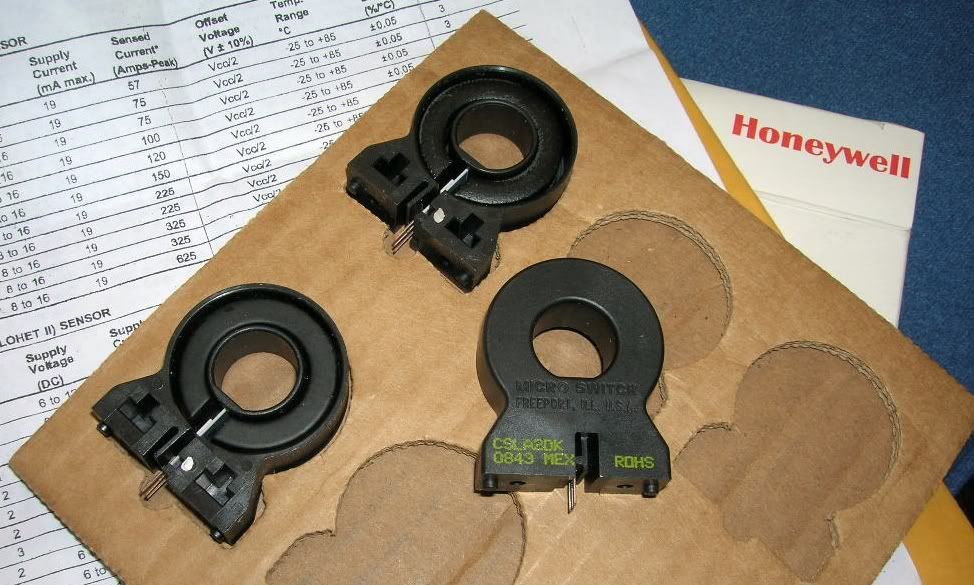 Honeywell Linear Current Sensor, CSLA2DK | eBay Wow, these got to my mailbox, less than 24 hours after placing the order..  After reading the specs (response time is FAST) and looking at the plot for DC current, http://scienceshareware.com/images/c...transducer.jpg For AC current, I have a feeling that a slow ADC is going to need some help.. Maybe a series diode with an cap & discharge resistor on the output..?. The pins are 0.1" spaced, so a short section of DIP socket should do for a connection.. The weather is way too nice to be working on this stuff.. We've been getting in a some bicycle miles this week! And tomorrow is going to be another good one! 
__________________
My hobby is installing & trying to repair mini-splits EPA 608 Type 1 Technician Certification ~ 5 lbs or less.. Last edited by Xringer; 12-03-11 at 07:55 PM.. |

|

|
|
11-08-11, 03:10 PM
|
#12 |
|
Lex Parsimoniae
Join Date: Feb 2009
Location: Woburn, MA
Posts: 4,918
Thanks: 114
Thanked 250 Times in 230 Posts
|
I just edited the first post above, since I forgot to show the source of the PCB.
The CAI controllers on Ebay aren't real expensive. Mine was $38 shipped. Remote monitor control temp humidity I/O WebControl X10 | eBay My only gripe about the board so far, is the lack of any serial port.. (And the firmware to drive it).
__________________
My hobby is installing & trying to repair mini-splits EPA 608 Type 1 Technician Certification ~ 5 lbs or less.. Last edited by Xringer; 11-11-11 at 11:49 PM.. Reason: It's CAI, not CIA!! |
|
|
|
|
11-11-11, 11:49 PM
|
#13 |
|
Lex Parsimoniae
Join Date: Feb 2009
Location: Woburn, MA
Posts: 4,918
Thanks: 114
Thanked 250 Times in 230 Posts
|
No temperature sensors in the mail yet.. But I did get the 8VDC power supply.
Just to be safe, before using on the CAI board, I checked the voltage. It was 12.1 Volts! 8V AC DC Power Supply Adaptor Adapter 8V 500mA US Plug | eBay They are sending a replacement.. In the meantime, I'll keep using the 9V supply. It's close to 8v and the 5v regulator isn't getting hot. I've been reading about the DS18B20 1-wire temp sensors, and it seems that using 3 wires (+5, Ground & Data) works best for long runs. I've heard that network cables work pretty well, due to the twisted pairs. So, I'm thinking of running network type cables with RJ45 connectors for the 8 temperature sensors, humidity sensor & the 3 analog inputs. For the DS18B20 sensors, I'll use one pair for the data and ground, and both conductors in another pair for the +5v. I'll also be running three cables with 12V, to power the 3 current sensors. (My spare 12V supply will come in handy). Not sure how many of the TTL (8)inputs and (8)outputs I'll be using, but I'm going to set up the TTL inputs on a screw terminal, so I can get at them after I'm got the system all buttoned up. I'm thinking of using some of the TTL I/O to communicate with another Coridium Corporation - ARMexpress Controller (It's gathering dust) programmable controller (uses basic), that has a serial output, that can drive a small text display, for easier human interfacing. As an alternative, I'm also thinking of using a Morse code human interface, but I'm not so sure my wife will like hearing the system beep too much..  I've seen these things cheap on Ebay.  Seems like a good way to connect the 8 temperature sensors in parallel off one line.
__________________
My hobby is installing & trying to repair mini-splits EPA 608 Type 1 Technician Certification ~ 5 lbs or less.. Last edited by Xringer; 11-12-11 at 02:12 PM.. Reason: Adding pic |
|
|
|
|
11-12-11, 09:53 AM
|
#14 |
|
Lex Parsimoniae
Join Date: Feb 2009
Location: Woburn, MA
Posts: 4,918
Thanks: 114
Thanked 250 Times in 230 Posts
|
The DS18B20 heat sensors came in this morning (now that Veterans Day is over).
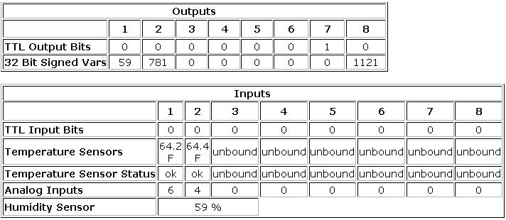 I stuck a couple of them into the CAI board's terminal right away. In the setup, both of their addresses showed up in each selection box. Meaning, these can be placed in any order on the display boxes. Your programs have to refer to the temp readings with the I/O identifiers T1,T2 ..to T8 The readings are displayed in Decimal format, but within a program, you use whole numbers, so if I wanted to compare T1 with 64.8 degrees, I would use the number 648. You can mix up the C & F selection.. If you want to. Today, I want to mount the humidity sensor inside of some kind of rain resistant inclosure, that will allow some air flow. The wires on the part are very thin and I'm flexing them way too much.. I would hate to break such an expensive part, ($17.90 USD) before I got it working outdoors.. 
__________________
My hobby is installing & trying to repair mini-splits EPA 608 Type 1 Technician Certification ~ 5 lbs or less.. |
|
|
|
|
11-12-11, 03:15 PM
|
#15 |
|
Lex Parsimoniae
Join Date: Feb 2009
Location: Woburn, MA
Posts: 4,918
Thanks: 114
Thanked 250 Times in 230 Posts
|
 Trying to figure out a good cable plan for the (4 pair) cables. 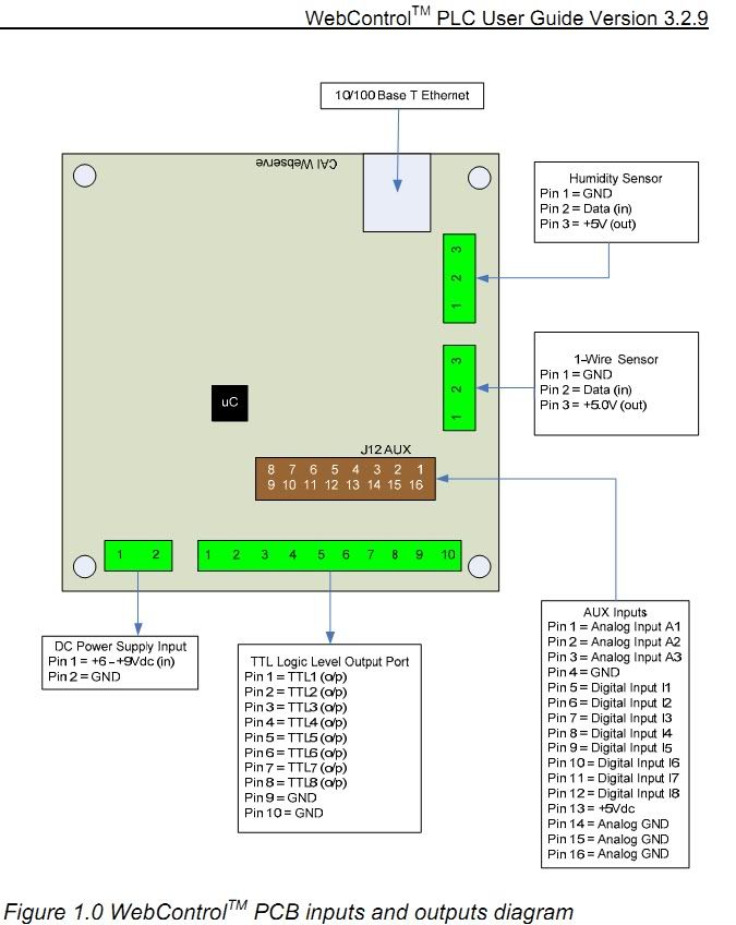 T & H sensor cable 1 ground (common to board 5V & outboard 12v PS). 2 data (DS18B20 temp sensors) 3 ground (Common to 1 above) 4 analog humidity sensor 5 ground (Common to 1 above) 6 +5v from board 7 ground (Common to 1 above) 8 +12V (add-on PS) (this power un-used for now) ~~~ Current Sensor cable 1 ground (common to board 5V & outboard 12v PS). 2 analog A1 3 ground (Common to 1 above) 4 analog A2 5 ground (Common to 1 above) 6 analog A3 7 ground (Common to 1 above) 8 +12V (add-on PS) ~~~ TTL Output cable (SSR compatible)! 1 TTL1 2 TTL2 3 TTL3 4 TTL4 5 TTL5 6 TTL6 7 ground 8 +5v from board Note: (TTL 7&8 used for X10 RF transmitter). ~~~ TTL Input cable #1 For reading device status (1 or 0) 1 Ground 2 Digital Input I1 3 Ground 4 Digital Input I2 5 Ground 6 Digital Input I3 7 ground 8 +5v from board (for pull-up resistor, if needed). TTL Input cable #2 For reading device status (1 or 0) 1 Ground 2 Digital Input I4 3 Ground 4 Digital Input I5 5 Ground 6 Digital Input I6 7 ground 8 +5v from board (for pull-up resistor, if needed). Digital Input 7 & 8 will be used to read two toggle switches. (PCL control inputs).
__________________
My hobby is installing & trying to repair mini-splits EPA 608 Type 1 Technician Certification ~ 5 lbs or less.. |
|
|
|
|
11-15-11, 12:09 AM
|
#16 |
|
Lex Parsimoniae
Join Date: Feb 2009
Location: Woburn, MA
Posts: 4,918
Thanks: 114
Thanked 250 Times in 230 Posts
|
Tested one of the current sensors tonight.
http://scienceshareware.com/articles...ent-sensor.pdf My sensors are CSLA2DK versions and they are good for 400 amps! (3 uSec response time). I'm using a 12vdc power supply, so my Zero DC bias voltage is at 6 volts. (Not 4v as shown) This evening, I put 3 turns of wire (125vac @ 10amps) though the core. My oscilloscope display a 6 volt DC signal with a superimposed sinewave, of only 2 vac peak to peak. It was going up to 7 volts and dropping down to 5 volts. (at 60hz). Since the CAI board's Analog inputs are 0 to 10vdc with 1023 resolution, That means the resolution is about 0.01v per bit. So, 2 volts are going to have a range of only 200 bits.  Using 200 bits to monitor 0 to 10 amps would be pretty course. But, the bad news.. The CAI board can't read AC voltages (peak), without a lot software overhead. I'll have to convert the AC output from the sensor, to DC. To capture the +&- magnitude of the whole 60hz waveform, I'm thinking of feeding the sensor's signal though a capacitor, into a full-wave bridge. (Voltage doubler).  This should give the CAI board a larger +DC voltage input to work with. The hole in the core is 0.625" ID. So, adding up to about 10 of loops of 12G wire is going to be feasible. Ten turns would really increase the sensitivity. Maybe from 400a down to 40a.?. I'm hoping to be able to use most of the full range of the analog input, (Which is clipped at 9v?), because the +6vdc bias will be blocked out. Only when AC current is passing, will DC signal be produced. It would be great if I could get these working at 0 to 8vdc, to represent 0 to 16 Amps, .. Half scale is 512 bits, so if I could get 8A to cause a 512 output..?.
__________________
My hobby is installing & trying to repair mini-splits EPA 608 Type 1 Technician Certification ~ 5 lbs or less.. |
|
|
|
|
11-28-11, 10:08 AM
|
#17 |
|
Lex Parsimoniae
Join Date: Feb 2009
Location: Woburn, MA
Posts: 4,918
Thanks: 114
Thanked 250 Times in 230 Posts
|
Found a neat output buffer for 4 of the TTL outputs.. $2 a channel..
 4 Channel 5V Relay Module For Arduino PIC ARM AVR DSP | eBay 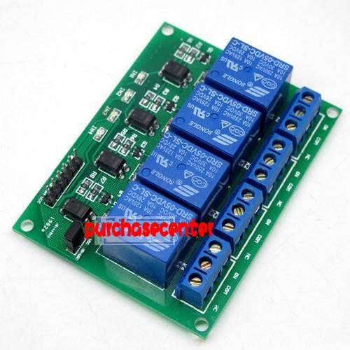 The board came in today and it looks real nice.. There is one shorted jumper plug on the board. Maybe for trouble shooting? It removes the JD-Vcc power from the driver transistors, (if removed). Those 10A 250vac contacts might be able to handle some pretty big loads. If placed in parallel, maybe even HVAC equipment...
__________________
My hobby is installing & trying to repair mini-splits EPA 608 Type 1 Technician Certification ~ 5 lbs or less.. Last edited by Xringer; 12-12-11 at 09:44 AM.. |
|
|
|
|
12-13-11, 08:20 PM
|
#18 |
|
Supreme EcoRenovator

Join Date: Mar 2009
Location: Portland, OR
Posts: 4,004
Thanks: 303
Thanked 723 Times in 534 Posts
|
Have you been able to write any PCL code that will make your webcontrol board respond to any change in sensor status?
In other words, have you been able to make it do anything? -AC_Hacker
__________________
I'm not an HVAC technician. In fact, I'm barely even a hacker... |
|
|
|
|
12-14-11, 07:36 AM
|
#19 |
|
Lex Parsimoniae
Join Date: Feb 2009
Location: Woburn, MA
Posts: 4,918
Thanks: 114
Thanked 250 Times in 230 Posts
|
Yeah. I wrote a routine that sent me an email when the temperature went above a selected set-point.
I also wrote some routines that averaged the humidity over a time span, to get rid of the LSBs dance factor. I'm not sure, but the bright on-board LED that flashes @1hz (heartbeat signal), might be pulling the Vcc around and affecting the ADCs. After all the sensors are connected, I hope the Vcc will be more stable. If not, I'll de-solder the flashing LED. Or put a larger resistor in series with it. It's not difficult to program, since the firmware(machine code) that does the actual 'reading' of the (3) ADCs, (8) TTL ports, (8) temperature & (1) Humidity is embedded. As is code for the (6) TTL output ports.Controlling those bits is as easy as SET OP6 1 or SET OP6 0, which can turn an SSR on or off. The language works a lot like a Basic interpreter. Not much bit-banging is needed. The difficult part of this job is getting all the parts together and finding the time to sit down and assemble the sensors & wiring harness. I have most of the hardware now. Just need to pick up a few small parts at Radio Shack..(For interfacing the current sensors). Now that the radon level at my work bench seems safe, I'll be able to get something done.. But, tis the season.. So it might be a while..
__________________
My hobby is installing & trying to repair mini-splits EPA 608 Type 1 Technician Certification ~ 5 lbs or less.. |
|
|
|
|
12-14-11, 11:53 AM
|
#20 | ||
|
Supreme EcoRenovator
Join Date: Mar 2009
Location: Portland, OR
Posts: 4,004
Thanks: 303
Thanked 723 Times in 534 Posts
|
Quote:
Quote:
Also, have you tried a really fat capacitor in parallel with the output of your power supply? Also, there is a technique called 'binning' where the datalogger or WebControl board will add up the results of several successive reads, send that data sum on for subsequent processing. Then your spreadsheet or whatever you use would do the division, where high quality floating point is available. -AC_Hacker
__________________
I'm not an HVAC technician. In fact, I'm barely even a hacker... |
||
|
|
|
 |
|
|


 Linear Mode

