
|
 03-02-15, 09:53 AM
|
#131 |
|
Lex Parsimoniae

Join Date: Feb 2009
Location: Woburn, MA
Posts: 4,918
Thanks: 114
Thanked 250 Times in 230 Posts
|
The best setpoint depends on the load of the motor.. (It's Resistance)
And, if want to insure the motor starts up in the morning, when the sun is weak. I've never had one of these things on a motor. So, I'm a novice on the settings topic.. Just try to find the point where it starts up reliably, and like you say, it should run full-throttle when the sun is bright. If you see the motor running really fast, and your PV voltage is high, like above the MPP voltage, that means your motor load is light.. Or the sun is extra bright..  In bright sun, you will not be able to draw a full 100W from your panel, if the motor is only using 75W (at max RPMs or gpm)..
__________________
My hobby is installing & trying to repair mini-splits EPA 608 Type 1 Technician Certification ~ 5 lbs or less.. |

|

|
|
03-02-15, 11:18 AM
|
#132 |
|
Lurking Renovator
Join Date: Feb 2015
Location: london
Posts: 12
Thanks: 1
Thanked 0 Times in 0 Posts
|
Ok I understand, so there's no way I can continuously have the panel operating at the maximum power point?
Because my aim was to always have the panel operating at the maximum power point 17.6V, as any voltage above means that the panel is not giving out the full 100W. |
|
|
|
|
03-02-15, 01:46 PM
|
#133 |
|
Lex Parsimoniae
Join Date: Feb 2009
Location: Woburn, MA
Posts: 4,918
Thanks: 114
Thanked 250 Times in 230 Posts
|
If your motor is drawing it's maximum current (and that current is equal to the max panel current) ,
any increase in voltage will increase the power your motor is using. Voltage x Amps = Power.. Watts.. Under normal sun condx, your max power out is at the MPP voltage. Remember that a DC motor at rest or just starting to turn, will draw a lot of power. While the motor is spinning up to full speed, it's still drawing more power than normal. Once the motor is at top speed, it needs less power to run at top speed. Just like a car gets bad MPG while accelerating (fast), but does better at a cruise speed. This is why your PV can't start up a big Directly Connected motor from a standing start. A panel that puts out 5A max might be putting 4.2A into that big Directly Connected motor, but the load is too great and the PV voltage is way down about 3.4Volts.. 3.4V x 4.2 =14.28W and not enough for your 75 watt motor.. The job of the pump optimizer is to show the PV panel a light load, and let the voltage increase, until it's high enough to zap the motor into moving.. 
__________________
My hobby is installing & trying to repair mini-splits EPA 608 Type 1 Technician Certification ~ 5 lbs or less.. |
|
|
|
|
03-03-15, 05:44 AM
|
#134 |
|
Lurking Renovator
Join Date: Feb 2015
Location: london
Posts: 12
Thanks: 1
Thanked 0 Times in 0 Posts
|
In your previous post you said:
If you see the motor running really fast, and your PV voltage is high, like above the MPP voltage, that means your motor load is light.. Or the sun is extra bright.. In bright sun, you will not be able to draw a full 100W from your panel, if the motor is only using 75W (at max RPMs or gpm).. So I cannot force my motor to draw 100W because the load is light, as I increase the load on the motor it will start to draw more power (due to the increased torque) and therefore the panel voltage will start to go closer to the MPP, as the panel is using more power. If I then remove the load on the motor the motor is using less power hence the solar panel voltage will increase (providing that the sun is bright) Is this terminology correct? |
|
|
|
|
03-03-15, 07:00 AM
|
#135 |
|
Lex Parsimoniae
Join Date: Feb 2009
Location: Woburn, MA
Posts: 4,918
Thanks: 114
Thanked 250 Times in 230 Posts
|
That's correct. If your pump runs dry, and uses less amperage, the voltage will climb.
If you wanted to, you might be able to hang a small charge controller on the panel to keep a 12V car battery charged up. I use my 500W array to charge my back-up batteries and heat hot water.. Since the backup bank needs very little charging, the charge controller allows the PV voltage to climb to max.. But, with the 13 ohm heater load, it can't really get very high. After the battery is fully charged, the water is well heated.
__________________
My hobby is installing & trying to repair mini-splits EPA 608 Type 1 Technician Certification ~ 5 lbs or less.. |
|
|
|
|
03-14-15, 07:53 AM
|
#136 |
|
Lurking Renovator
Join Date: Feb 2015
Location: london
Posts: 12
Thanks: 1
Thanked 0 Times in 0 Posts
|
Hello again,
Iv built the circuit and its working, I can see that with different levels of sunlight I can maximize the power going into the load by adjusting the pot. However I want to do some calculations and I am having trouble trying to calculate the voltage at which the comparator switches. How do you work out the voltage i have tuned the circuit to fire? |
|
|
|
|
03-14-15, 08:00 AM
|
#137 |
|
Lex Parsimoniae
Join Date: Feb 2009
Location: Woburn, MA
Posts: 4,918
Thanks: 114
Thanked 250 Times in 230 Posts
|
__________________
My hobby is installing & trying to repair mini-splits EPA 608 Type 1 Technician Certification ~ 5 lbs or less.. |
|
|
|
|
03-14-15, 08:29 AM
|
#138 |
|
Lurking Renovator
Join Date: Feb 2015
Location: london
Posts: 12
Thanks: 1
Thanked 0 Times in 0 Posts
|
Yes, iv used that formula, but the thing is you want to find the firing voltage so in this case its going to be the VCC of the voltage divider, so regardless of what values you plug into the equation your always going to get VCC equal to the PV voltage.
|
|
|
|
|
03-14-15, 09:30 AM
|
#139 |
|
Lex Parsimoniae
Join Date: Feb 2009
Location: Woburn, MA
Posts: 4,918
Thanks: 114
Thanked 250 Times in 230 Posts
|
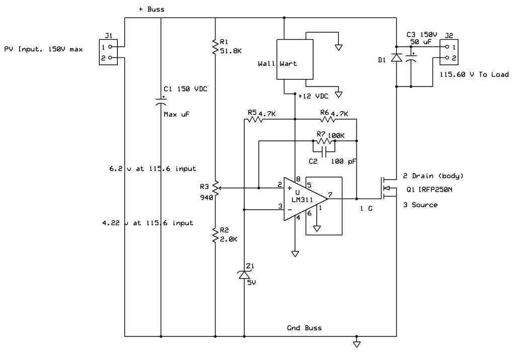 The voltage on pin 2 of the LM311 is going to be a tiny bit over 5V when the 311 comparator switches states. If Z1 is a 5.1 Zener diode, then LM311 will switch at a little over 5.1 v. When I did this diagram, I calculated the values of the voltage divider based on 70 to 150 volts from the PV.. The VCC (pin 8) of the LM311 must be kept constant, using a regulator. I used a standard 12V Chinese made inverter PSU.. Since it will output clean 12Vdc if fed with 90 to 250 volts AC, or 50 to 150 volts DC.. When you say VCC, I'm assuming you are talking about the power supply for pin 8 of the IC.. Anyways, measure the voltage on pin 3, and that's the voltage needed on Pin 2, to make the IC switch.. If the pin 2 voltage is lower than pin 3, nothing happens. The IC is really a simple level detector. I really don't have anything else to tell you about it.. 
__________________
My hobby is installing & trying to repair mini-splits EPA 608 Type 1 Technician Certification ~ 5 lbs or less.. |
|
|
|
|
03-14-15, 09:56 AM
|
#140 |
|
Lurking Renovator
Join Date: Feb 2015
Location: london
Posts: 12
Thanks: 1
Thanked 0 Times in 0 Posts
|
Sorry when i meant VCC i didn't mean the VCC of the IC
I meant the voltage going into the voltage divider. But it think iv got the concept now - assuming that you have a reference of 5V on the negative terminal of the comparator (pin 3) , if you adjust the pot so that you have 8V on the positive terminal of the comparator (pin 2) when the panel voltage is 20V, that will mean that your firing voltage will be 20-3 17V. Similarly if you adjust the pot so that you have 6 volts on pin 2 when panel voltage is 20 then your firing voltage will be 20-1 = 19V Is this correct? |
|
|
|
 |
|
|


 Linear Mode

