
|
 11-11-11, 02:47 AM
|
#981 |
|
Uber EcoRenovator
Join Date: Apr 2011
Location: Strathroy Ontario Canada
Posts: 657
Thanks: 9
Thanked 191 Times in 129 Posts
|
AC Hacker wrote:
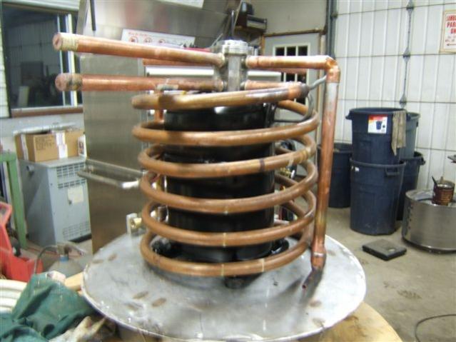
It would be helpful if we also knew: what the BTU rating of your compressor was? what is the water flow rate in each loop? how long the copper/PVC HX was? what was the temp of water in and out of each HX? what was the temp of refrigerant in and out of each HX? what do the details of the ends of each HX look like? In other words, how do you take the water from the HX and how do you take the refrigerant from the HX? If we had enough examples of homemade HX performance, then we could begin to build them with more confidence. Randen: The BTU rating for the compressor was 2T or 24,000 BTU The water flow for the testing 20 ltr/min or 4.5gal/min The length of copper tube for each HX is about 25 ft. I then trimmed 1 - 2 ft to fit The temp of the water in and out is a 2 C deg. gain or loss for either HX. The refrigerant Condensor in 65 C deg. out 40 C deg (all the heat is given up to the glycol/water) The refrigerant Evaporator in I did check but really frosty out 4 C deg and again all the heat had been taken up by the glycol/water. For the end of HX tubes I will have to post some drawings and photos. The effiency seems quite good I was very suprised. I believe that th HXs could be used with a larger compressor. The lenghts of tube where a guess and what I had on hand. The biggest thing is to always run the water/refrigerant counter-current. I will be busy installing the HP this week (it getting cold here)but after that I will post results with photos but better the results keeping me warm in the shop?? Randen |

|

|
| The Following User Says Thank You to randen For This Useful Post: | AC_Hacker (11-14-11) |
|
11-11-11, 07:37 AM
|
#982 |
|
Lex Parsimoniae

Join Date: Feb 2009
Location: Woburn, MA
Posts: 4,918
Thanks: 114
Thanked 250 Times in 230 Posts
|
Randen, I'm interested in the propane.
What was your source? If it was raw BBQ gas, did you do anything special (filters & etc)? Did you take any extra precautions? (With electrical contacts, leak detection & etc). If you have already posted about the above, please point me in the right direction. 
__________________
My hobby is installing & trying to repair mini-splits EPA 608 Type 1 Technician Certification ~ 5 lbs or less.. |
|
|
|
|
11-11-11, 08:02 AM
|
#983 | |
|
Supreme EcoRenovator

Join Date: Mar 2009
Location: Portland, OR
Posts: 4,004
Thanks: 303
Thanked 723 Times in 534 Posts
|
Quote:
Thank you for this information, it will be of great value to future builders. Sincerely, -AC_Hacker
__________________
I'm not an HVAC technician. In fact, I'm barely even a hacker... |
|
|
|
|
|
11-11-11, 08:44 AM
|
#984 |
|
Uber EcoRenovator
Join Date: Apr 2011
Location: Strathroy Ontario Canada
Posts: 657
Thanks: 9
Thanked 191 Times in 129 Posts
|
Xringer Wrote
What was your source? (of Propane) Yes BBQ propane Being this is a experiment I didn't go to any extremes like extra dryers to install the gas. There is a dryer on the system and I felt it should take care of any moisture. I did pull a vacuum on the system and left it sit for a couple days (to check for any leaks??) Then I just made up a hose and installed it. Actually I was suprized it didn't take much maybe 4 oz. One problem I had had was the scheider valve wasn't working on the high side and when I had removed the gauges I lost most of the charge. One interesting thing to note: The propane as it left the compressor it didn't have the smell anymore, it was odorless. One thing I intend to do is use (Solid State Relay) just in case. I feel that if it leaks the propane should dissappate. The GSHP is on the main level no basement for the propane to pool in. I don't believe there is enough there to cause much damage if any. All the conditions have to be met for something catastrophic. I will still sleep well. The thing I found most interesting is the performance of the little 2T: COP of 4.3 and output of 18KBTH/H The comercial unit I have at home 3 T R410 refrig. and COP 3.5 and Approx 18400 BTU/H Randen Last edited by randen; 11-11-11 at 08:54 AM.. |
|
|
|
|
11-11-11, 09:13 AM
|
#985 | |
|
Supreme EcoRenovator
Join Date: Mar 2009
Location: Portland, OR
Posts: 4,004
Thanks: 303
Thanked 723 Times in 534 Posts
|
Quote:
Xringer's concern is quite correct, especially regarding electrical contacts. At the very least, you should make sure you avoid arcing (electro-mechanical) relays. Solid State Relays are inexpensive and very reliable. The nature of refrigeration leaks is that they are usually small and slow, so critical mixtures are rare, but not unimaginable. Also, propane is heavier than air, so it will collect at floor level. Unless you have sealed your shop to something approaching passive house levels, you should be in the clear. Another issue to keep in mind is circuit-breaker sizing, very important... Printed on your compressor is a label that says something like "LRA 55". LRA stands for Locked Rotor Amps. This refers to the worst case condition, wherein the compressor motor is not able to turn but is still drawing current, and in the case above, 55 amps is what it will draw. Under no circumstances do you want to have a breaker larger than 55 amps, or whatever your LRA is. In this case, bigger is NOT better. There is also a figure available that signifies the running amps that your compressor normally draws, you want your breaker safely larger than that number, but smaller than the LRA limit. You'll want to make sure that the circuit your heat pump is on, is wired at least to the running amps level... somewhat bigger is better. Your compressor has a thermal overload protector, but it is too slow to respond to Locked Rotor situations.  You'll want some kind of thermostat control, there's the one I built which has a Solid State Relay, and uses a thrift store thermostat, and is quite accurate. This is pretty simple to build, and will get you going. But in the long run, a smarter controller would be better. Xringer has come across a pretty dandy controller that I think will answer the search I have had for a long time for a controller for a homemade heat pump.  Xringer has done a pretty good job of introducing the hardware, and has some examples of environmental measurement he has done with it. I think Xringer wants to measure and control his house, but this thing is just what the doctor ordered for controling your heat pump. It looks like you could configure it to do all sorts of advanced things like make sure that your heat pump stays within safe operating temperatures, pressures, and current draws. In fact, you could also have it act as a burglar alarm for you shop, if some one broke it, it could set off an alarm, and send you an email, too... how comforting. Regards, -AC_Hacker
__________________
I'm not an HVAC technician. In fact, I'm barely even a hacker... |
|
|
|
|
|
11-11-11, 09:18 AM
|
#986 | |
|
Supreme EcoRenovator
Join Date: Mar 2009
Location: Portland, OR
Posts: 4,004
Thanks: 303
Thanked 723 Times in 534 Posts
|
Quote:
-AC_Hacker
__________________
I'm not an HVAC technician. In fact, I'm barely even a hacker... |
|
|
|
|
|
11-11-11, 09:57 AM
|
#987 | |
|
Journeyman EcoRenovator
Join Date: Jan 2011
Location: Seattle
Posts: 326
Thanks: 109
Thanked 23 Times in 18 Posts
|
Quote:
Your'e making me feel like the little kid that tugs at his dads pant legs and say Dad, Dad, Dad. Again, what is the valve at the top of the picture that the lines go into. Inquiring minds want to know............ Thanks, Geo |
|
|
|
|
|
11-11-11, 10:42 AM
|
#988 |
|
Lex Parsimoniae
Join Date: Feb 2009
Location: Woburn, MA
Posts: 4,918
Thanks: 114
Thanked 250 Times in 230 Posts
|
Now that I have the current sensors, I can add to my wish list..
1. Indoor temp 2. Outdoor temp 3. Basement temp 4. Hot water boiler temp 5. Sanyo#1 5/8" refrigerant line 6. Sanyo#1 1/4" refrigerant line 7. Sanyo#2 5/8" refrigerant line 8. Sanyo#2 1/4" refrigerant line Analog Input1 Current use of Sanyo #1 Analog Input2 Current use of Sanyo #2 Analog Input3 Currently unassigned. Actually, once the power use of the Sanyo systems are being monitored, I can control the power going into Sanyo#1, since it's max power limiter http://ecorenovator.org/forum/applia...r-limiter.html breaker is plugged into X10..
__________________
My hobby is installing & trying to repair mini-splits EPA 608 Type 1 Technician Certification ~ 5 lbs or less.. |
|
|
|
|
11-11-11, 04:29 PM
|
#989 | |
|
Supreme EcoRenovator
Join Date: Mar 2009
Location: Portland, OR
Posts: 4,004
Thanks: 303
Thanked 723 Times in 534 Posts
|
Quote:
I think you meant to post this entry to this thread. -AC_Hacker
__________________
I'm not an HVAC technician. In fact, I'm barely even a hacker... |
|
|
|
|
|
11-11-11, 05:47 PM
|
#990 |
|
Uber EcoRenovator
Join Date: Apr 2011
Location: Strathroy Ontario Canada
Posts: 657
Thanks: 9
Thanked 191 Times in 129 Posts
|
Fellow eco renovators I will continue to post some drawings and photos of the GSHP. The controls for now will have to wait. I plan to put the open contact relay into a container and seal it for now. I fully intend to utilize the solid state relays and a timer for the completed controls. The timer would be good idea for false starts. There are so many nice open source controls avalible now like that Xringer is looking at.
The circuit breaker is just over the run current to take care of any locked rotor problem. FLA-15A, LRA-33A. I hope this weekend to have it installed and running. Night-time lows are dropping below 30 F deg. We are making the cover for the GSHP to tidy it up and providing an ample area for the controls. Randen |
|
|
|
 |
| Tags |
| air conditioner, diy, gshp, heat pump, homemade |
|
|


 Linear Mode

