
|
 09-20-11, 05:25 PM
|
#1 |
|
Lex Parsimoniae

Join Date: Feb 2009
Location: Woburn, MA
Posts: 4,918
Thanks: 114
Thanked 250 Times in 230 Posts
|
I was watching this video, as I was looking at the diagram below..
The Animated Cycle - YouTube The location of the coils, (left & right) corresponds nicely to the diagram. 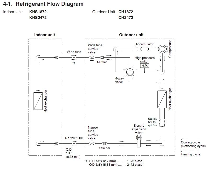 And, since my Condenser coil is on the left in Heating mode, and the Evap coil is on the right, it was easy to understand the explanation (as it applied to the Sanyo). The dotted lines are the heating cycle. I think now, I can understand why the "narrow tube" is used on the Liquid Line and the wide tube needs to be wide, so it can handle the volume of high pressure gas. Maybe someday, the box labeled Indoor Unit will be a gas-to-water HX. (For the Repaired Sanyo outdoor unit). |

|

|
| The Following User Says Thank You to Xringer For This Useful Post: | ThomSjay (09-20-11) |
|
09-20-11, 11:23 PM
|
#2 |
|
Helper EcoRenovator
Join Date: Mar 2011
Location: Sarnia, Ontario, Canada
Posts: 91
Thanks: 8
Thanked 2 Times in 2 Posts
|
I had to sit and think a while before I finally understood the flow in both directions. Thanks.
__________________
TomS |
|
|
|
|
09-21-11, 08:28 AM
|
#3 |
|
Lex Parsimoniae
Join Date: Feb 2009
Location: Woburn, MA
Posts: 4,918
Thanks: 114
Thanked 250 Times in 230 Posts
|
For a guy interested in this topic, my understanding of heat pumps is pretty basic.
I had to pause and rewind a few times, (I'm old) and make some notes on my diagram, but things are clearer now. It's a lot easier to look at my system and visualize the 'flow' of the R410A and know what state it's in, on which side of the Expansion valve etc. I'm in the middle of testing the repaired outdoor Sanyo unit, so it's nice to know more about how things actually work, instead of looking at it as a Black-Box, as is often done in the electronics field. |
|
|
|
 |
|
|


 Linear Mode

