
|
 02-20-16, 09:49 PM
|
#201 |
|
Supreme EcoRenovator
Join Date: Jan 2010
Location: elizabethtown, ky, USA
Posts: 2,428
Thanks: 431
Thanked 619 Times in 517 Posts
 |
If it were mine, I would much rather run a lineset to the air-source outdoor unit. While I was at it, I would run a phone line or cat 5 cable with the lineset so I could connect the air unit to some sort of controls. Wouldn't be super cheap, but at least It's a one-time expense. And the big box stores in town carry them.
|

|

|
|
02-21-16, 08:59 AM
|
#202 |
|
Journeyman EcoRenovator

Join Date: Apr 2015
Location: Oxford, MS USA
Posts: 496
Thanks: 69
Thanked 87 Times in 61 Posts
|
I stink at explaining things, so I do the second thing I am worse at, drawing.
Maybe this will explain it better. The bright red and blue lines are the line set right now, they run in the attic and throw ceiling that I can not get to. The power is run in the walls and attic as well. Power labeled in yellow. This is what it would take to bring it all into the greenhouse. When I was only thinking of using water source that was doable, but adding another line set and all that brazing would be a nightmare. Plus really long runs that might be too much for my oil return. I can just barely get under the stairs, and would be tying into the power already going to the air handler. The wire is ok though because it was set up to use strip heat, that I have completely taken out. Also I didn't draw the second air handler in the picture. Darker red and blue lines are the new line set. This is what I am thinking will be easiest and best, I'll need to build a heated box for the water coils and pump though. That is the only down side to doing it like this.
__________________
שְׁמַע יִשְׂרָאֵל ה' אֱלֹהֵינוּ ה' אֶחָד |
|
|
|
|
02-21-16, 12:24 PM
|
#203 |
|
Supreme EcoRenovator
Join Date: Jan 2010
Location: elizabethtown, ky, USA
Posts: 2,428
Thanks: 431
Thanked 619 Times in 517 Posts
|
I think I have half a clue about the nature of this install. I looked through some of your other threads and found a few pics of your house. Am I correct in assuming you don't have a basement? Judging from the close proximity to your pond, if you did have a basement, it would leak constantly if not hermetically sealed. So that rules out going through the bottom? Slab or teensy weensy crawl space present?
I saw plenty of pics of the greenhouse and pond side of the house, but not much of the side where you are planning on tying everything together. There were a few close-ups of the DHW DX compressor set up right next to your existing outdoor unit. But not too much as far as overall shots of what goes where. I did see that what you have now is right up next to an entry door, so not much room to grow that direction. I asked my wizard at hand about this one. He looked into his crystal ball (labeled "smirnoff") and my phone, looked back at me, and said: "Keep it simple, stupid. The guy has two options: A: Build a doghouse around the little one and put everything in there. If it gets sealed and insulated, the running compressors will keep everything warm when it's cold. Might need a summer vent, though. B: Build a bridge between the two outdoor units and put everything in there. Don't sacrifice airflow. Lemme see that other pic... OK, it looks like the disconnect was mounted too low anyway. That might be a code violation. If a paver tile will fit in between the unit and the house, there is enough room for everything to fit. Default to option A on the inside, pretty skin on the outside. J channel with tapcons into the wall and sheet metal would be my first choice. Make sure the top has slope that runs away from the house..." followed by irrelevant expert details. Following the short and sweet answer were some half-drunken ramblings about the pics we looked at. I will omit that part. You know how construction contractors and maintenance mechanics and such can be about something they didn't actually do. So, Then I changed the subject after saying thanks and a toast. I hope his insight helps. The pics and drawings you provided in your past projects made it super easy for me to seek advice. The skilled craftsmen in general have sort of an "x-ray vision" for this stuff. Without your scribblings and shots, dude would not have shown interest at all. This is why I am always begging people for pics: you never know when they will come in handy, but if they aren't present no one can see them. If you want to make it look super sanitary, there are a couple of siding products that look just like real brick. Neither one is super expensive. Wood or foam: 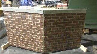 Google SIP panel or sandwich panel. Less common, more expensive. 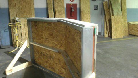 Plastic:  Sample product. Available all over the place, less expensive, not structural. 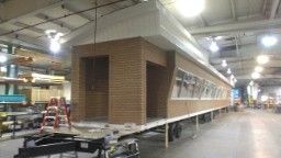 OK, back to the project at hand:  Not working on heat pumps today... |
|
|
|
|
02-21-16, 12:59 PM
|
#204 |
|
Journeyman EcoRenovator
Join Date: Apr 2015
Location: Oxford, MS USA
Posts: 496
Thanks: 69
Thanked 87 Times in 61 Posts
|
So we can agree that running it into the greenhouse is to complicated?
I would love to find a 6 ton condenser with a bad compressor. One fan sounds much easier and a more compact unit. Thanks for the suggests to make it look better. Here are some pictures. First is looking down the hall. Air handler to the right, HP water heater and outside red door by the outside unit to the left. This is looking the reverse direction into the closet with the air handler. This is the outside door that is to the left of the outside unit. This is the outside unit. This is the distance between the unit and the house. No basement, its on a slab. No attic access over head either, have an upstairs of half of it and vaulted ceiling over the rest. Thanks for taking the time to look into this.
__________________
שְׁמַע יִשְׂרָאֵל ה' אֱלֹהֵינוּ ה' אֶחָד |
|
|
|
|
02-21-16, 04:10 PM
|
#205 |
|
Journeyman EcoRenovator
Join Date: Apr 2015
Location: Oxford, MS USA
Posts: 496
Thanks: 69
Thanked 87 Times in 61 Posts
|
Oh and there is no code here. So I'm free to do as I wish on my own property. lol
What if I found one of these 6 ton package units with a blown compressor, and just put everything in it?
__________________
שְׁמַע יִשְׂרָאֵל ה' אֱלֹהֵינוּ ה' אֶחָד Last edited by MEMPHIS91; 02-21-16 at 06:12 PM.. |
|
|
|
|
02-21-16, 08:26 PM
|
#206 |
|
Supreme EcoRenovator
Join Date: Jan 2010
Location: elizabethtown, ky, USA
Posts: 2,428
Thanks: 431
Thanked 619 Times in 517 Posts
|
Ok, so from this set of pics, it looks like you have a chase running overhead from the air handler, over your kitchen cabinets, out to where you ran the lineset for the dx water heater. My big question is: did they put your breaker panel on the other side of the window, or in the air handler closet wall? I've seen it both ways. Either way, there's lots of stuff running through that chase already. No need to further stuff that area with anything.
The big dog outdoor units like in your pic tend to favor lots of parallel cap tubes or a big txv and distributor for metering. Make sure and look before you buy. |
|
|
|
|
02-21-16, 09:03 PM
|
#207 |
|
Journeyman EcoRenovator
Join Date: Apr 2015
Location: Oxford, MS USA
Posts: 496
Thanks: 69
Thanked 87 Times in 61 Posts
|
Sadly the line set runs into the brick wall and straight up into the small attic space above the kitchen and then sideways into the chase the runs across the hall then down the wall into the air handler.
The breaker panel is to the left of the small window that is to the left of the red door in picture 4 of the picture post. It is directly behind the meter base. I was assuming I would need a 4 ton txv on the 6 ton coils right? Or are they close enough it doesn't matter?
__________________
שְׁמַע יִשְׂרָאֵל ה' אֱלֹהֵינוּ ה' אֶחָד |
|
|
|
|
02-21-16, 11:19 PM
|
#208 |
|
Supreme EcoRenovator
Join Date: Jan 2010
Location: elizabethtown, ky, USA
Posts: 2,428
Thanks: 431
Thanked 619 Times in 517 Posts
|
Ok, so is there anything in the space above the kitchen cabinets? It looked like the drop ceiling in the hallway starts about the same place. Then again, that makes too much sense. Why not run stuff so its impossible to service? No matter, just mod the system outdoors where you can reach everything important.
With the 6 ton unit, you could either swap out the whole txv, try the one that's installed, or just change the orifice. Depends on a lot of things. |
|
|
|
|
02-22-16, 04:54 PM
|
#209 |
|
Journeyman EcoRenovator
Join Date: Apr 2015
Location: Oxford, MS USA
Posts: 496
Thanks: 69
Thanked 87 Times in 61 Posts
|
I'm thinking just keep everything equal and get the same txv i'm using on the water and indoor coils.
So my brain has been in high gear today and here is what I'm thinking on. Why not have 2 solenoids? One on the water coil and one on the outside air coil. Have audiuno taking temps and which ever has the high temp gets used? This to me seems simple and 100% all the time. The txvs are not going to work right 100% of the time due to changing temps. Been thinking on the programming as well. Since I'm taking a temp reading anyway I can tell the compressor to start up at a certain % based on how cold/hot it is inside vs outside and the ramp up if more is needed. Also in cooling mode I could be measuring indoor humidity and have the indoor fan start up and run slower to increase condensation and dehumidification if the humidity gets over around 50%. http://www.fancollectors.org/info/speed.htm Would something like this work to control the fan speeds? I would need 2 per fan, indoor and out. One for 50% and one for 75%. AC Motor Fan Dimmer Speed Control 1000W 220 240V Triac Assembled Kit | eBay Here is a drawing I have so far, without solenoids. I really like finding/building from scratch the outdoor unit that way I can build everything and simply swap out the txv inside and some electric work and swap out the outside unit. Instead of 2-3 days of running line sets and brazing TONS to use the unit I have now.
__________________
שְׁמַע יִשְׂרָאֵל ה' אֱלֹהֵינוּ ה' אֶחָד Last edited by MEMPHIS91; 02-22-16 at 06:18 PM.. |
|
|
|
|
02-25-16, 07:45 AM
|
#210 |
|
Journeyman EcoRenovator
Join Date: Apr 2015
Location: Oxford, MS USA
Posts: 496
Thanks: 69
Thanked 87 Times in 61 Posts
|
Found this I would need 2 of these. https://surpluscityliquidators.com/p...alve-coil.html
Also I want to heat my hot water during cooling. I already have the coil in the tank, so why waste heat? I would need a 1/4 solenoid and a check valve. Here are some rough diagrams, the (/_) is the solenoid. HA = heating air, HW = heating water, CA = cooling air, CW = cooling water.
__________________
שְׁמַע יִשְׂרָאֵל ה' אֱלֹהֵינוּ ה' אֶחָד |
|
|
|
 |
| Thread Tools | |
| Display Modes | |
|
|


 Linear Mode

