
|
 09-04-09, 07:21 AM
|
#111 |
|
Administrator

Join Date: Aug 2008
Location: Germantown, WI
Posts: 5,525
Thanks: 1,162
Thanked 374 Times in 305 Posts
|
Do you think that your inverter is the bottleneck in the system?
__________________
Current project - To view links or images in signatures your post count must be 0 or greater. You currently have 0 posts. To view links or images in signatures your post count must be 0 or greater. You currently have 0 posts. & To view links or images in signatures your post count must be 0 or greater. You currently have 0 posts. |

|

|
|
09-09-09, 10:59 AM
|
#112 | |
|
Apprentice EcoRenovator

Join Date: Dec 2008
Location: mid michigan
Posts: 191
Thanks: 0
Thanked 0 Times in 0 Posts
|
Quote:
|
|
|
|
|
|
10-04-09, 05:33 PM
|
#113 |
|
Apprentice EcoRenovator
Join Date: Dec 2008
Location: mid michigan
Posts: 191
Thanks: 0
Thanked 0 Times in 0 Posts
|
changed the array angle to the fall position saturday. I was supposed to do it in late august
 . Been having some dreary days lately and getting cold kinda early too. September production totaled only 23.93 kwhrs, or about 798 whrs per day. . Been having some dreary days lately and getting cold kinda early too. September production totaled only 23.93 kwhrs, or about 798 whrs per day. |
|
|
|
|
11-12-09, 03:07 PM
|
#114 | |
|
Lex Parsimoniae

Join Date: Feb 2009
Location: Woburn, MA
Posts: 4,918
Thanks: 114
Thanked 250 Times in 230 Posts
|
Quote:
So, if I wanted to see how much power my 230V heat pump was using, I could cut one of the 230 lines and run it through the Neutral pins of my Kill-a-Watt? And tie the Hot (smaller) pin to ground? And, of course I would multiply the watts etc by two.. I'm just picturing a 120v extension cord, cut in half, plugged into the KillaWatt and patched into a 230v line..  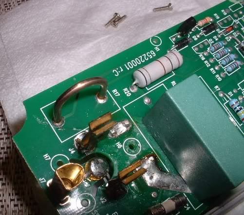 Well, that was easy. I just took a look at the PCB and found a Resistance loop wire in between the neutral In and Out. There is a trace on both ends of the Loop wire that lead up the PCB. So, it seems like it might be pretty easy to wire my P4460 up to measure wattage on a 230 line.. Just need an old extension cord.. Last edited by Xringer; 11-12-09 at 03:39 PM.. Reason: Adding picture |
|
|
|
|
|
11-13-09, 08:20 AM
|
#115 | |
|
Apprentice EcoRenovator
Join Date: Dec 2008
Location: mid michigan
Posts: 191
Thanks: 0
Thanked 0 Times in 0 Posts
|
Quote:
Last edited by jwxr7; 11-13-09 at 08:23 AM.. |
|
|
|
|
|
11-13-09, 08:26 AM
|
#116 |
|
Apprentice EcoRenovator
Join Date: Dec 2008
Location: mid michigan
Posts: 191
Thanks: 0
Thanked 0 Times in 0 Posts
|
Here are some #s for October. It was the worst month so far, very gloomy and cold. The average was only around 450 watthrs/day.
|
|
|
|
|
11-13-09, 02:56 PM
|
#117 | |
|
Lex Parsimoniae
Join Date: Feb 2009
Location: Woburn, MA
Posts: 4,918
Thanks: 114
Thanked 250 Times in 230 Posts
|
Quote:
in case the whole-house monitor idea doesn't work out. Cheers, Rich |
|
|
|
|
|
11-13-09, 07:03 PM
|
#118 | |
|
Apprentice EcoRenovator
Join Date: Dec 2008
Location: mid michigan
Posts: 191
Thanks: 0
Thanked 0 Times in 0 Posts
|
Quote:
I've been following your heat pump thread and really like what I see. A very neat system  . I have one concern; that the start up amps might exceed the killawatt's 15 amp rating. I've done it before intermittantly without it failing, but it will beep at you when it happens. It could fail if the current is alote higher than 15 amps or a little higher than 15A for a long period of time though. Your compressor is a variable speed type driven by an inverter (I think) so maybe it won't be a huge problem to start? Maybe you could use an analogue clamp on ammeter and see what it looks like while starting before you hook up the killawatt. . I have one concern; that the start up amps might exceed the killawatt's 15 amp rating. I've done it before intermittantly without it failing, but it will beep at you when it happens. It could fail if the current is alote higher than 15 amps or a little higher than 15A for a long period of time though. Your compressor is a variable speed type driven by an inverter (I think) so maybe it won't be a huge problem to start? Maybe you could use an analogue clamp on ammeter and see what it looks like while starting before you hook up the killawatt.Last edited by jwxr7; 11-13-09 at 07:28 PM.. |
|
|
|
|
|
11-13-09, 07:43 PM
|
#119 |
|
Lex Parsimoniae
Join Date: Feb 2009
Location: Woburn, MA
Posts: 4,918
Thanks: 114
Thanked 250 Times in 230 Posts
|
All the motors are DC, and they seem to be doing a soft-start when they come on..
I think in-rush current might be a problem during power-up from the circuit breakers or during a power blink. My guess is, the 230 AC hits some diodes and then some capacitors with a little jolt.. 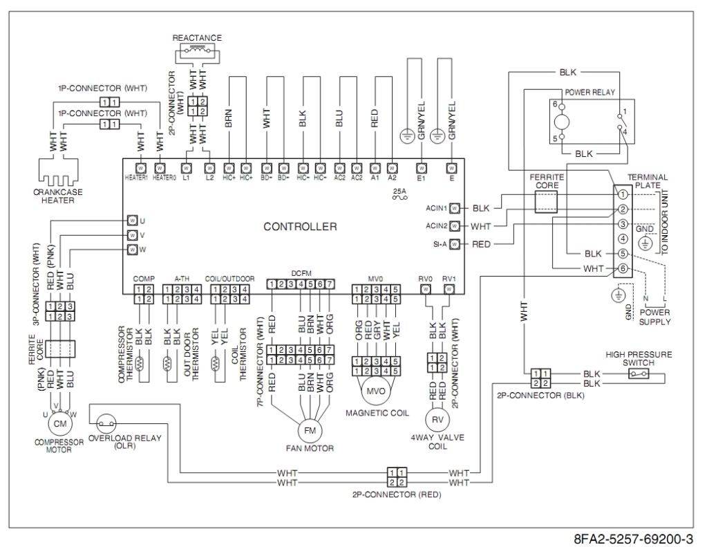 Notice the N & L (middle right side) go right into the PCB.. The high voltage DC supply is always live. On or Off aka standby. The Power Relay is going to stay on continuously, unless there is a problem. Overload or pressure. Edit: Now that I've read what I typed.. My advice is to open the breakers during any vacations.. Why leave HV DC on and the control boards running.?. Last edited by Xringer; 11-13-09 at 07:48 PM.. Reason: advice |
|
|
|
|
11-14-09, 09:31 AM
|
#120 | |
|
Apprentice EcoRenovator
Join Date: Dec 2008
Location: mid michigan
Posts: 191
Thanks: 0
Thanked 0 Times in 0 Posts
|
Quote:
Is there a schematic showing the power supply leading to the schematic you posted? Because it shows only one AC line "hot" wire going to the control circuit. Your system is connected to your house wiring with a 4 wire system right (2 hots, 1 Neutral,1 Gnd)? I was just thinking about a problem you may encounter trying to use the killawatt this way. If your system isn't balanced, you won't be able to accurately measure system power using one hot. There could be a 120v part in the system drawing from one hot side and using the neutral as a return. If it's hard to tell from the schematic, then this could be checked with a clamp on style ammeter while the unit is operating. If both hots have the same current and the neutral has zero then it's balanced and the killawatt idea should work well. The Gnd wire shouldn't ever have any current unless there is some kind of insulation fault . Check these currents in all types of operation modes. |
|
|
|
|
 |
| Tags |
| electric, solar |
|
|


 Linear Mode

