
|
 11-15-10, 05:53 AM
|
#1 |
|
Apprentice EcoRenovator
Join Date: Feb 2010
Location: Milford, DE
Posts: 106
Thanks: 5
Thanked 9 Times in 9 Posts
|
My plan for this thread is to log the installation of the Fujitsu multisplit system listed in the title. I have a poor track record with keeping consistent updates in logs/blogs, but we'll see how it goes here
 Background I am in the (slow) process of building my own home from the ground up. It's a 1000sqft, 2 bed/2 bath, single story residence. I am doing as much work as possible myself, to learn and save money. I am 29 years old, with little previous construction experience prior to this. I have ~10 years computer programming experience, and have an associate degree in electronic/electrical engineering. You could say I'm out of my element, but I'm good at self-study, and have spent the past few years reading much on residential design and construction practices. I'm in good health and have ambition, so things are going well so far. The House It is a single story home with a conditioned crawlspace and ventilated attic. The crawlspace has 2" XPS rigid foam insulation on the exterior side of a 4' tall 8" block wall foundation. The floor system is composed of 2x10s of #1 southern yellow pine, and the band/rim joist sits recessed on the wide 2x10 PT sill plate which caps the block wall and extends over the exterior insulation. To the outside of the recessed band joist is 2" XPS again. I'll attach the original cross section submitted for the city building permit. Slight changes were made from these plans - the ceiling joist to rafter connections were changed (i'll attach that detail too.) |

|

|
|
11-15-10, 06:16 AM
|
#2 |
|
Apprentice EcoRenovator
Join Date: Feb 2010
Location: Milford, DE
Posts: 106
Thanks: 5
Thanked 9 Times in 9 Posts
|
House blog & pics
I've kept a blog running during construction: vinnie Picasa albums with construction pics: Picasa Web Albums - mrd999 - vinnie pics b... Picasa Web Albums - mrd999 - vinnie pics b... Heat pump selection During the home design process, I read about these inverter heat pump systems and wanted to determine if it would be feasible to use one. There are a few traditional-type split systems on the market with inverter compressors - I believe they're called 'IQ Drive' - but from what I've read the equipment is expensive. I ran Manual-J load calculations using Rhvac. From this I ascertained a cooling load around 11kbtu and heating load around 19kbtu. A 1.5 to 2 ton system would meet this. To be fair, 2 tons (24kbtu) is oversized for a 11kbtu cooling load. But I assume with the inverter systems' ability to ramp down compressor speed, it will comfortably handle a 50% design load. It's not ideal, but it allows me to use a single heat pump to meet cooling & heating design loads. If I were using a traditional fixed speed heat pump, I'd likely order a 1.5 ton heat pump with supplemental heat - propane perhaps, as natural gas isn't available here. That fact was a factor in my selection of this equipment. It's illegal in Delaware to perform any gas piping without a plumber's license, even on your own home. As I'm doing all the work on this home myself, I wanted to forgo the need to contract a licensed plumber. Staying with an all-electric system allowed this, and the inverter system made it practical to go this route. Most of the inverter systems found in the market here have a single indoor unit, and they are wall-mounted. However there are also multizone systems with multiple indoor units connected to an outdoor unit. There are also various types of indoor units available aside from wall-mounted units. One type is a ductable blower. I am using ducted indoor units because I want the HVAC system installation to give the appearance and function of a typical system found around here, which is ducted with registers throughout the home delivering conditioned air. I'm mounting the blowers in the conditioned crawlspace and running ductwork to registers. The Fujitsu system I selected is called "ceiling concealed" and is meant to be installed in the ceiling, typically above a drop ceiling in a light commercial environment. It has a small blower and is optionally ducted. However, after looking at the heat & fan specs, I determined it would suit my needs. There are other blower units available from other manufacturers with a stronger blower actually designed for the type of install I'm doing, but the closest in price to this unit I found was about $700 more. This seemed the best bang for the buck. |
|
|
|
|
11-15-10, 06:39 AM
|
#3 |
|
Apprentice EcoRenovator
Join Date: Feb 2010
Location: Milford, DE
Posts: 106
Thanks: 5
Thanked 9 Times in 9 Posts
|
Duct design
Here's the design for the ductwork: There are two blowers and each has its associated return air and supply. The ductwork is shown colored by zone. Both returns run directly as a trunk to the blower. From there, the supply runs along a trunk until at the end where they will transition into flex duct runs. The flex duct runs follow a large radius bend until their trajectory is in-line with their outlet. Each line then runs directly to the outlet, bends up and meets the register at a register boot. The trunk and its transitions needs to be fabricated. I would prefer to use metal, but I can't afford a brake right now and would need to rent it far too long to be affordable. So, I plan to use duct board for the trunk. The fabrication tools should be under $150 all together. I am still hunting for a good price. This design would have any seasoned duct designer/installer raising their eyebrows. One main goal of the design is an extremely low pressure drop. The fans in the blowers have a low static pressure limit of 0.16 inches of water. This is very low, but doable. My return grilles are very large. The air path from return to blower is straight. The dark purple trunk return has to make a 180 degree turn, however. This was unavoidable due to the restrictions of the floor plan. I am going to use turning vanes in the two 90s for this line. I'm boxing out a space in the master closet to allow these turns to have maximal cross sectional area. You can see the hole in the floor and wall for this here: 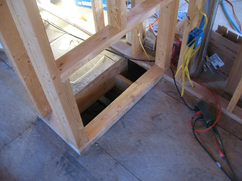 To run from the trunk to the outlets, I came up with a scheme to allow a large-radius bend in flex duct lines. I have theorized this will allow a lower pressure drop than if I ran typical "take-offs" at a 90 degree angle from the trunk. To reach this conclusion, I extrapolated data I found for flex duct friction losses in sweeping bends, and other anecdotal data found on the web. I'm taking a chance on this part of the design, but I like to live on the edge and be innovative, so what the heck! To make these turns, I'm using a thin sheet of "hard board" - $8 per 4x8 sheet - ripped 2ft tall. A few 2x4s hanging down from the floor joists will support the bend in the sheet, forming a curve. The flex duct is then stretched along with the support at its inner throat. The blowers are already hanging in the crawlspace: 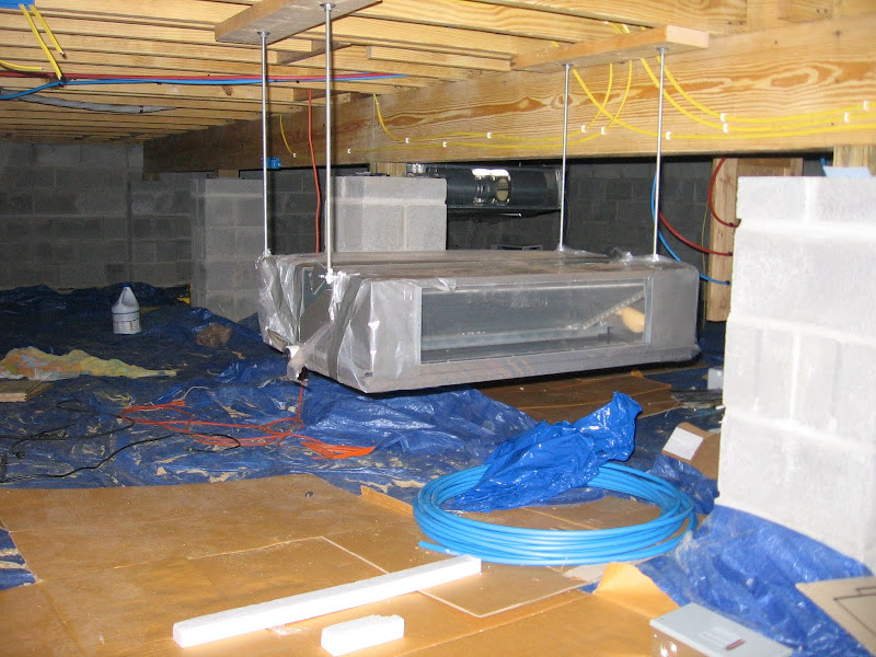 Once I finish electrical and plumbing, I'll begin constructing the ductwork. In the mean time I still need to source the trunk & flex material, and the fabrication tools. |
|
|
|
|
11-15-10, 06:49 AM
|
#4 |
|
Apprentice EcoRenovator
Join Date: Feb 2010
Location: Milford, DE
Posts: 106
Thanks: 5
Thanked 9 Times in 9 Posts
|
Return filters
The blowers come with filters that attach directly to the return side. I've decided to instead use larger filters placed in the return grilles. These are larger for a lower pressure drop, and will be accessible from the main floor - so they're more likely to be replaced regularly. From my readings, the return filter is typically the largest pressure-reducing element of a duct system. Simply increasing the filter area reduces pressure drop. The type of filter used also affects the static pressure drop. Electrostatic filters do a great job of filtering small particles, and they are washable/reusable. However, they tend to induce a large pressure drop. Thick "media filters" can do a good job without great pressure drop, but they are expensive and take up more space than a typical 1" filter. The return filter grilles I've purchased take a 1" filter, and I'll likely be using a typical simple filter due to cost and pressure considerations. |
|
|
|
|
11-15-10, 07:28 AM
|
#5 |
|
Apprentice EcoRenovator
Join Date: Feb 2010
Location: Milford, DE
Posts: 106
Thanks: 5
Thanked 9 Times in 9 Posts
|
Zones
If you look at the design for the duct system, one blower's return air comes from the rear of the house, and supplies air to the front. The other blower's return air comes from the front of the house, and supplies air to the rear. In a zoned system, the supply and return air should both run to the same zone. Obviously, my design isn't zoned. The indoor blowers can be configured as a single zone, controlled at a single wall-mounted controller. I chose this design mainly because it allows a more direct path of airflow (air likes to go straight.) I also hope this will allow a more even distribution of conditioned air. Typically, heating/cooling loads on a house change throughout the day, mostly affected by the orientation of the sun. The front of my house is due west, so as the sun travels its daily east-to-west path, the loads on the front and rear of the house will change. If the front and rear were zoned separately, then each blower would need to meet the brunt of the load on the house at some point during the day. While the combination of blowers meet the peak design loads of the home, an individual unit only meets half that load. By mixing the blowers in a single zone, I hope they'll better cope with a load that's concentrated at one end of the house, as the air mixes back & forth from front to back. |
|
|
|
|
11-15-10, 08:38 AM
|
#6 |
|
Apprentice EcoRenovator
Join Date: Feb 2010
Location: Milford, DE
Posts: 106
Thanks: 5
Thanked 9 Times in 9 Posts
|
Refrigeration experience
I have little experience working with refrigeration equipment, so this is all new to me. I did spend a few years in the Army working in a shop shared with refrigeration repair guys, so I got some exposure there. A guy spent a few minutes showing me how to braze copper.. but it's been a while! The Fujitsu manual recommends seamless copper, so it looks like I'll just be doing some flares. I've ordered some tools I'll need, and some others still need to be found. I found the threads here on minisplit installations invaluable! Tools & equipment The installation manual for the blowers indicate a need for a disconnect switch at each blower, and from looking at NEC (electrical code) requirements, I think it's pretty much required, although arguments could be made that they're not necessary. I ordered two Bryant manual motor controllers - these are 3-pole switches and they can fit a standard electrical box. Of course I paid like $10 more than this listing and didnt get the enclosures, just the switches. Lot of 2 BRYANT 30003 Manual Motor Controller 30A, 600V - eBay (item 290359539311 end time Dec-07-10 14:52:23 PST) You need a 3-pole switch to disconnect the two power legs and the signal line (NEC requires all ungrounded conductors to break in a disconnect, and the install manual shows a 3-pole.) I ordered an adapter to convert the 1/2-20 UNF service port to a standard 1/4 schrader. R410a, AIR CONDITIONER ADAPTER, USED ON "MINI-SPLITS" - eBay (item 150499002145 end time Nov-25-10 12:34:39 PST) I ordered a Robinair 15150 vacuum pump. Robinair 15150, 15300, and 15500 1.5, 3, and 5 CFM VacuMaster Vacuum Pump - on Sale at the Test Equipment Depot I ordered some manifold gauges, although I suspect I might have gotten by without them. LX1001A R410A Refrigeration Manifold Gauges 36" Hoses - eBay (item 350405911551 end time Nov-19-10 06:46:15 PST) And why don't these inverter systems have a service port on the hot side? Got a Fieldpiece SVG2 micron vacuum gauge. Fieldpiece SVG2 Standalone Vacuum Gauge NEW: FIEL18 Climate Doctors I also ordered a set of spring tube benders. I understand the service port uses a schrader valve. I've got experience with schrader valves from when I used to ride my bike all the time as a kid. And I remember that fitting being very leaky whenever I was connecting/disconnecting something from it. I certainly don't want any leakage after pulling a vacuum. So, I wondered if someone sells a fitting that screws onto a schrader valve, but that has a manual control to depress the core, such that the valve could be closed before unscrewing the fitting. I would think such a thing would exist especially for HVAC work, but I had trouble locating anything. I came across this yellow jacket 18993. I dont know if the 18993 is what I wanted, but I'm hoping. HVACR-Tools.com: Yellow Jacket 18993 Gas Control Valve I still need to get some Nylog, a crowfoot adapter for my torque wrench, and flaring tools for 1/4 & 3/8 copper lines. I think I'm just going to pull a vacuum and forgo a nitrogen test. If it holds vacuum then I'll assume it's good.. Unless the nitrogen test isn't all that much more work? I'm not sure where I'd even get a nitrogen tank, how much it would cost, if I'd need special adapters, etc.. Last edited by mrd; 02-20-11 at 05:56 AM.. |
|
|
|
|
11-16-10, 04:54 AM
|
#7 |
|
Apprentice EcoRenovator
Join Date: Feb 2010
Location: Milford, DE
Posts: 106
Thanks: 5
Thanked 9 Times in 9 Posts
|
Reference documents
I have a truly massive digital reference library on HVAC. Here are a few good links that would benefit anyone interested in learning more. Smart and Cool - This dispells common HVAC misconceptions and offers excellent system design information. Design Process for Sizing - This reviews how Building America homes had their HVAC systems designed in conjunction with RHVAC software - although you could reference this with other Manual J calculation applications. HVAC System Pressure Relief - This shows how to balance air pressure between rooms when you have a central return in a duct system. Accessing Sealed Refrigeration Systems - This is an excellent reference on service valves and gauge manifolds. Designing VRF Systems - Specifics on using systems with variable refrigerant flow, such as inverter systems. |
|
|
|
|
11-16-10, 06:44 AM
|
#8 |
|
Administrator

Join Date: Aug 2008
Location: Germantown, WI
Posts: 5,525
Thanks: 1,162
Thanked 374 Times in 305 Posts
|
Nice to see another mini-split project. I think your documentation skills are doing quite well so far.
 If you do have problems with pressure drop in the system you could always use some sort of additional blower to compensate.
__________________
Current project - To view links or images in signatures your post count must be 0 or greater. You currently have 0 posts. To view links or images in signatures your post count must be 0 or greater. You currently have 0 posts. & To view links or images in signatures your post count must be 0 or greater. You currently have 0 posts. |
|
|
|
|
11-16-10, 09:23 AM
|
#9 |
|
Lex Parsimoniae

Join Date: Feb 2009
Location: Woburn, MA
Posts: 4,918
Thanks: 114
Thanked 250 Times in 230 Posts
|
I found the nitrogen test pretty easy, since I already had a paint-ball air tank.
They are cheap and come with a 800-900 PSI regulator built in. Hooking one up to your manifold isn't much of a problem.. But, there is a work-around, that's fairly common in these kinds of installations. After you have done your vacuum testing, and everything looks good, and you are at the 'release the 410a' step. Stop right there. Read over your manual, it might even tell you how to do this pressure test. You release 410a into the line-set for 10 or 15 seconds, and then shut off the valve. If there is a loose fitting, you won't suffer a big loss of refrigerant. Now is the time to check all your flare fittings with soapy water. You might also have a stethoscope handy to 'listen' to the fittings. I use one from an old BP tester. Just removed the big disc on the end of the hose. Or, you can just use 3' of flexible tubing, holding one end to your ear and the other near the fittings. That worked very well for me, when I was on the phone with Sanyo, I was able to 'pipe' the hissing sound to the phone. Making my case for a leak right above the compressor. Anyways, when you don't detect any leaks, then you can release the 410a for real. I did this 401a pressure test with my Sanyo (both times I installed) and it gave me confidence in the flares. I guess you could do this test with a manifold attached and just watch the pressure for a couple of days.. Since my line-set was pre-flared and was so simple (4 connections), I tried to keep it simple and not have to waste any 410a in the hoses. |
|
|
|
|
02-20-11, 06:23 AM
|
#10 |
|
Apprentice EcoRenovator
Join Date: Feb 2010
Location: Milford, DE
Posts: 106
Thanks: 5
Thanked 9 Times in 9 Posts
|
More tools
I did order an eccentric 45 flaring tool and an 8 piece flare crowfoot set. Hooray for cheap ebay tools Blindly flaring where no man has flared before I've learned a few things this week. I ran the soft copper refrigerant lines in the crawlspace from each blower to the outdoor unit. Each lineset has a 3/8"OD and 1/4"OD line. I used my spring tube benders, but I think I should have applied some light oil in them first. I found they made very light scratches on the pipe.. not nice on pipe with an already extremely thin wall. The 1/4 line has a wall of 0.030".. I used my eccentric flare tool kit to make the flares. The pipe cutter tended to leave an imploded end at the pipe. I'm not sure if this is because I'm tightening the cutter too quickly, or if the cutting wheel isn't sharp enough, or perhaps this is normal.  I then use the reaming tool quite vigorously with the pipe opening pointed downward to let gravity remove most of the copper bits. Then I use the deburring end on the cutter to smooth any roughness, and tap the pipe a few times to try to ensure the shavings are out. I really don't like this process with all the copper bits, seems an easy way to contaminate the system. Perhaps I should have done more experimenting with pipe cutting before proceeding... 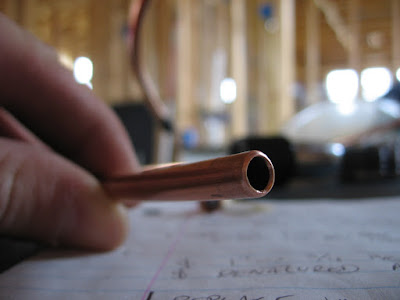 The flaring tool was then clamped onto the pipe, with about 1-3mm protruding, as this is what the engrish instructions stated to do. 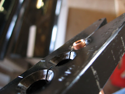 Then I crank down the handle until the clutch kicks, then unscrew, unclamp and remove. A few times I turned the handle an additional turn or so after the clutch, to make sure the clutch really did kick. O_o I don't think this was appropriate, the head keeps turning down when you do this. I just assumed the head only turned with the clutch engaged, but I found later on that it does keep turning.... .  The clutch only provides a torque reference to prevent crushing the copper edge too thinly, it doesn't actually prevent you from doing so. This might explain why two of my 1/4 inch flares simply snapped off at the base with a gentle nudge after they were attached.. The first few flares, I also forgot to put the flare nut on first.. Doh. 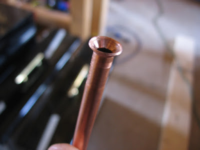  I coated all the faces, backsides, and what-have-yous of the flares with Nylog. I then torqued down the flare nuts to the specified torque settings. I used my torque wrench with the crow foot adapter at a 90-degree angle. I also was prepared to use the torque conversion formula with the adapter at 180-degrees, but I thought a 90 orientation would be simpler. In retrospect, I wonder if 180-degree orientation is more accurate..? As I said, two of the 1/4 flares snapped at the base of the flare, an event which induced quite a bit of frustration and worry. I'm not sure if this was due to me turning the flare tool past clutch-kick, as I only did this a few times, and I'm not sure on which flares. I also wonder if the use of Nylog reduced the friction so much that reaching the specification torque crushed the flare too thin. I found reaching the spec torque required a surprising amount of force, and as I tightened the flare nut down the pipe was easily shifted off-axis inside of the nut to a small degree, and ended up slightly crooked when it finally tightened.. I had no idea such simple flares could prove to be so finicky. I think also verifying the diameter of the outer edge of the flare fit snugly inside the nut would have been prudent. At the time of making these flares I had some concern, but they seemed to hold. Last edited by mrd; 02-22-11 at 06:27 AM.. Reason: pics |
|
|
|
 |
| Tags |
| diy, heat pump, install, mini-split |
|
|


 Linear Mode

