
|
 12-20-10, 07:09 AM
|
#21 |
|
Helper EcoRenovator
Join Date: Dec 2010
Location: Jamaica
Posts: 59
Thanks: 0
Thanked 0 Times in 0 Posts
|
Can you please tell me exactly what i should change to increase the current rating to at least 12amp for the mini max? Or can you redraw the circuit so that it can handle more current at the output
(at least 12amp). Also on your unbuilt hack of the same rig where you have 80V max PV input voltage. Can the circuit still operate off a lower voltage say for example a 12V panel and still have the capability to operate up to 80V if a bigger size panel is used? __________________ Last edited by fabieville; 12-20-10 at 07:18 AM.. |

|

|
|
12-20-10, 10:05 AM
|
#22 | |
|
Lex Parsimoniae

Join Date: Feb 2009
Location: Woburn, MA
Posts: 4,918
Thanks: 114
Thanked 250 Times in 230 Posts
|
Quote:
If you Google up irfp150n datasheet, you will find it can do about 100A if you can keep it at room temperature. http://www.irf.com/product-info/data...a/irfp150n.pdf And about 30A at 100 deg C.  So, if you only run it at 12A, you shouldn't need to attach a heat sink. The reason I put 80v max on my diagram (unbuilt project), is because I figured that was the limit my panels could do. Now that it's cold, I see them at 85v every time the sun comes out..  The irfp150n is designed to run at 100v max (V(BR)DSS Drain-to-Source Breakdown Voltage). So, I would stay away from any PV source that went too close to 100V. Cloud-Edge voltage power jumps could put you over the limit.. My best guess right now (untested) is that 85v is gonna be okay. Will it work at a lower PV voltage.?. My little 10W 12V panels are actually able to make 20 to 23 volts. With peak power at 17 to 18 volts. 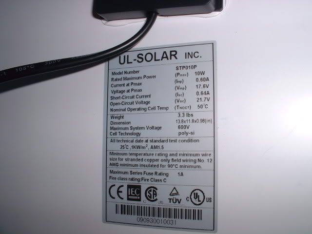 I think it should work as drawn. If you PV voltage is lower, there might be a problem with the Zener diodes. I picked 12 & 15 volt Zener, because I have some. Actually those could both be changed to 10v Zeners. And perhaps the 5v Zener could be changed to something lower? Like 3V maybe. The important thing to remember is the gate input protection Zener should be about 10V. I picked 12V, because I have them.. (I think the MAX limit is +or- 20v). The second thing to remember is the series resistor's wattage. R1, R2 & R3 are voltage dividers, and should be large enough for your high voltage PV. Let's say you had an 50v PV. The total resistance of R2 & R3 is 32k. 50V / 32,000 is 0.00156 amp. 34.37v across R1 and 15.6v across the pot. (V=RxA or E=RI in school). The power dissipated by a resistor is equal to the VxA (P=IE) So, 0.00156A x R3@15.6v=0.024 watts. So, a 1/8w resistor would be fine. At 100v, you could use a 1/4w.. R1 is a 10k with the PV voltage across it, minus the 15 volts of the Zener. A 50V PV means R1 gets 35v. 35 / 10,000 = 3.5ma (or 0.0035A) P=IE (or P=IsqR) gives us 35x0.0035= 0.1225w (~1/8 watt), so it would be best to use a 1/4w resistor there.. For 50v PV.. And 1/2W for 100v..  I guess this means that I can still remember a little of Ohms law..  But, this circuit, using these parts has not been tested yet. So, there might be a few bugs to iron out.. Seems like there always is.. I might be using resistors at overly high values.?. Maybe I need to scale them down and increase the wattage of them.?. Not sure yet. Here's a handy chart..  Last edited by Xringer; 12-20-10 at 10:16 AM.. Reason: many many typos |
|
|
|
|
|
12-20-10, 06:35 PM
|
#23 |
|
Apprentice EcoRenovator
Join Date: Nov 2010
Location: Oklahoma City
Posts: 155
Thanks: 58
Thanked 17 Times in 14 Posts
|
Xringer, check out this...it may help
fieldlines dot com/board/index.php/topic,144675.msg978354.html#new |
|
|
|
|
12-20-10, 06:38 PM
|
#24 |
|
Helper EcoRenovator
Join Date: Dec 2010
Location: Jamaica
Posts: 59
Thanks: 0
Thanked 0 Times in 0 Posts
|
so basically you are saying i can connect my 30amp 12V solar array to this circuit without making any modifications because the mosfet can handle it?
|
|
|
|
|
12-20-10, 07:01 PM
|
#25 | |
|
Lex Parsimoniae
Join Date: Feb 2009
Location: Woburn, MA
Posts: 4,918
Thanks: 114
Thanked 250 Times in 230 Posts
|
Quote:
I think it can. The BUK455 used in the Mini-Max pump board is rated for 60A. The IRFP150N that I will be using are rated pretty close to that. These transistors can be used in pulsed mode for a lot higher current. If you can build the circuit and run it at 10 or 15 Amps, while watching the MOSFET temperature, you can decide if you are going to need a heat sink or not.. 30 Amps is a lot of current. You will need to keep the current carrying lines of your circuit, short and fat. This circuit might cause RFI/EMI signals that will interfere with radio signals. You might want to consider adding some by-pass caps to the lines. Cheers, Rich |
|
|
|
|
|
12-20-10, 07:02 PM
|
#26 | |
|
Lex Parsimoniae
Join Date: Feb 2009
Location: Woburn, MA
Posts: 4,918
Thanks: 114
Thanked 250 Times in 230 Posts
|
Quote:
That kinda looks like simulation software. A lot to learn.. It might be faster for me to just build what I need and see if it works..?. |
|
|
|
|
|
12-20-10, 07:10 PM
|
#27 |
|
Helper EcoRenovator
Join Date: Dec 2010
Location: Jamaica
Posts: 59
Thanks: 0
Thanked 0 Times in 0 Posts
|
when you say bypass caps or you talking electroyltic caps or the ceramic looking caps that can connect either way and when you say to add them to the lines do you mean to both the input and the output lines?
|
|
|
|
|
12-20-10, 07:30 PM
|
#28 | |
|
Lex Parsimoniae
Join Date: Feb 2009
Location: Woburn, MA
Posts: 4,918
Thanks: 114
Thanked 250 Times in 230 Posts
|
Quote:
The only lines not bypassed are optical fibers..  It's basically adding caps from noisy lines to ground. High frequency voltages (Spikes) will see those caps as a low impedance and short to ground. I've used .001, .01 & .1 uF disc caps with some degree of success. Just adding them across the + & - lines can cut transistor switching noise too. But also connecting caps to each side (of + & -) to a good ground is important. |
|
|
|
|
|
12-20-10, 07:57 PM
|
#29 |
|
Helper EcoRenovator
Join Date: Dec 2010
Location: Jamaica
Posts: 59
Thanks: 0
Thanked 0 Times in 0 Posts
|
when you stated in a much earlier posts that "These transistors can be used in pulsed mode for a lot higher current" does the mini maximizer circuit operates on pulses of currents at all times? and if yes does that mean that the fet should be on a suitable heatsink just incase i get very large peak current going to to the fet. I am correct?
|
|
|
|
|
12-20-10, 09:15 PM
|
#30 |
|
Lex Parsimoniae
Join Date: Feb 2009
Location: Woburn, MA
Posts: 4,918
Thanks: 114
Thanked 250 Times in 230 Posts
|
Nope, not if the load is well matched to the PV, where the PV is voltage is at it's sweet spot.
It's maximum power point. (About 17.6v on the little 10w panel shown above). That transistor will stay turned fully ON all the time.. But, when the clouds come over (and the panel can't deliver continuous full power to the load) , the pulses will start back up. The spec shows the IRFP150N has 0.036 ohms (Max) when it's fully turned on. If you were running 30 amps, there would be (30 x 0.036) about 1 volt across the transistor. Ouch! That's 30 watts of heat! Yeah, a good heat sink is going to be needed. Think 30 watt soldering iron! I'm glad my PV never puts out more than 8A.. (8A x 0,036=0.288w). I don't need no stinking heat sink..  Cheers, Rich |
|
|
|
 |
|
|


 Linear Mode

