
|
 05-19-16, 01:31 AM
|
#11 |
|
Supreme EcoRenovator
Join Date: Jan 2010
Location: elizabethtown, ky, USA
Posts: 2,428
Thanks: 431
Thanked 619 Times in 517 Posts
 |
OK, that looks like a 1/3 or less horsepower compressor. Just take the evaporator out of the water and air-cool it with a fan for now. Stick a manifold gauge on your service fittings and purge the hoses by cracking each side open until gas flows out the center hose. Connect your bottle and open the high-side valve. start the unit and let the extra charge condense back into the propane cylinder. The cylinder will heat up as the extra gas shrinks back into the bottle.
When you get enough gas out, the suction pressure will drop enough to freeze the evaporator. With a cap tube metered rig, the suction pressure should drop to 20-30 PSIG when the unit first starts up. A small section of the evaporator should try to freeze. This small section will grow as head pressure and liquid build up against the cap tube. Measuring how much of the evaporator is at constant temperature and making sure it is never flooding the compressor is very important!After 10-15 minutes of operation, 20 - 30 DegF of suction superheat is not uncommon. In this application, you want the evaporator to be larger than the condenser in surface area so it can pull an ample amount of heat from the air. If it were mine, I would probably just use the stock evaporator and add some 1/4" tubing to the end of it for efficiency. Then again, I might use both the stock evaporator and condenser tubes for the evaporator. The tubing you have looks like it is rather large diameter for such little capacity. A longer piece of 1/4" or smaller tubing would be more efficient and easier to get inside your water tank. How much propane did you charge it with? Does the original unit show how much R-22 it was charged with? You should weigh in the charge with a digital scale. If you don't have one, go buy one at your local speedy mart. 10 bucks well spent. With that size of rig, i would imagine it would only take a couple of Oz of R-290. |

|

|
|
05-19-16, 05:47 PM
|
#12 |
|
Helper EcoRenovator

Join Date: May 2016
Location: SE Wisconsin
Posts: 55
Thanks: 3
Thanked 14 Times in 10 Posts
|
Thanks for taking the time to give all that detailed info.
The original dehumidifier label said 7.25 oz of r22. I don't have a digital scale but ordered one today on Amazon. Her's what I did today 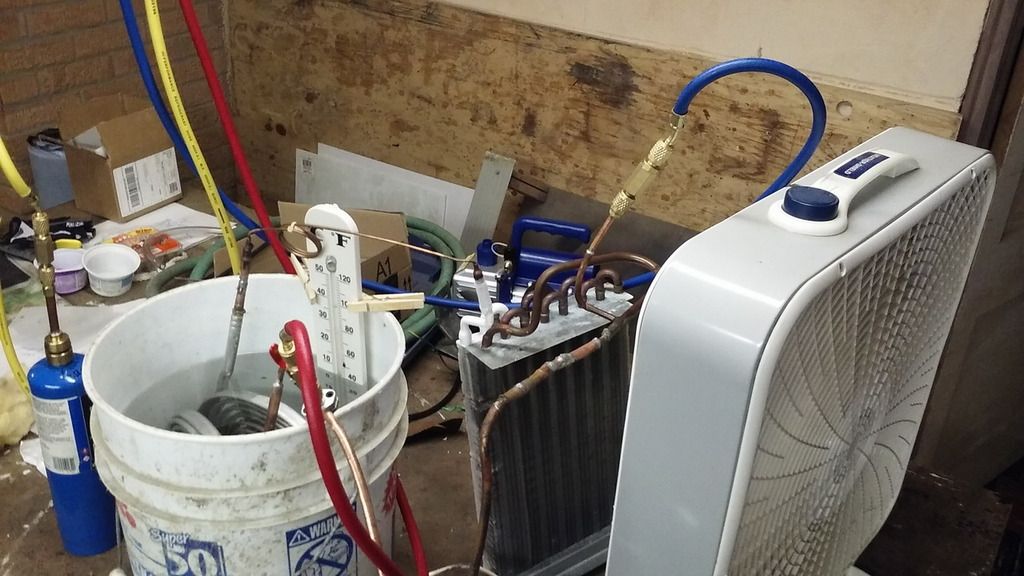 I replaced the evaporator with one from a 5000 btu ac and set a fan next to it. I recharged and got it working fairly well in spite of the sloppy workmanship. After about 15 min I got these measurements. Plow--20psi Phi-145psi T into condenser-140F T out of evap-58F amb-61F T into evap was so frosty that I couldn't get good temp reading T of water in bucket 60-70F All temps taken by pressing thermocouple to bare copper tube with insulation between my finger and thermocouple. The temps don't jive with the pressures. The tubes are bare so that might be an issue. I don't have confidence in the pressures. Maybe my propane is contaminated. So I learned that a coil of bare copper tube submerged in 4 gal of water won't be good enough for the evaporator. I was pleased with how well this worked with a real evaporator even though I don't trust the pressures. I have another dehumidifier that I will use for my water heater--I will improve my workmanship when I start the actual project. So far this is for practice and learning. |
|
|
|
| The Following User Says Thank You to IdleMind For This Useful Post: | jeff5may (05-20-16) |
|
05-20-16, 08:03 AM
|
#13 |
|
Supreme EcoRenovator
Join Date: Jan 2010
Location: elizabethtown, ky, USA
Posts: 2,428
Thanks: 431
Thanked 619 Times in 517 Posts
|
Awesome progress! Now that the thing works, run it for awhile and watch what happens with the pressures and temperatures (evaporator, compressor discharge and suction, water, etc.) as the unit pours heat into the water. To get a general idea of all the factors at play, this is the best way to dispel the mystery and to match the theory with reality. Cap tubes are slow enough that you can sit back and watch what is going on. Even if something isn't perfect, nothing will get hurt as long as refrigerant and oil are circulating.
Since you don't have a scale, an easy way to get the unit in the rough ballpark of where you want it goes like this: From deep vacuum, put some gas in the unit with the compressor not running. The pressure will equalize at whatever the vapor pressure is at ambient temperature. Close both valves on your gauge set and put your gas bottle in an ice water bath. Start the compressor and watch the suction pressure drop. Once it gets below about 50 PSIG, crack the suction side valve open slightly so the pressure stays around 35-40 psi. If the gas cylinder has cooled sufficiently, it will prevent the rig from being severely overcharged. With this size of a rig, it won't take much refrigerant at all. Close the valve and watch what happens. The discharge pressure will not rise much at all if your water tank is cold. Some freezing of the air coil is normal during these conditions. As your tank temperature rises, discharge pressure will rise. If your discharge temperature rises high enough so you can't touch it without getting burned, the unit is undercharged. The high discharge temperature is a product of a compressor starving for refrigerant suction gas. R290 is not as bad as R22 in this regard, so running your rig a little undercharged is not necessarily a bad thing compared to R22. But with an oversized evaporator, it should never be really full of actively boiling liquid (running a cap tube). When the water storage tank has heated above 120 degF (50 degC), your discharge pressure should be in the 250+ PSIG range. This is the best condition to set your system charge (and adjust your cap tube length if necessary). This is most likely the conditions in which the system will spend most of its time operating, so making sure the evaporator is cool enough to pull heat out of the air but warm enough so it doesn't freeze is very important. Good luck with your trials. Please let us know what you find, as well as any questions you might have. The learning curve for this subject is not shallow at all. Be safe! Last edited by jeff5may; 05-20-16 at 11:37 AM.. |
|
|
|
| The Following User Says Thank You to jeff5may For This Useful Post: | stevehull (05-20-16) |
|
05-20-16, 06:08 PM
|
#14 |
|
Helper EcoRenovator
Join Date: May 2016
Location: SE Wisconsin
Posts: 55
Thanks: 3
Thanked 14 Times in 10 Posts
|
jeff5may--that is an interesting way to think about the system, I read it several times and have a pretty good grasp on what you are saying, but feel like I still don't fully understand.
Anyway today I did take some data and put it into excel. Here's a photo, I wraped a towel around the water bucket because the fan is blowing cold air on it. 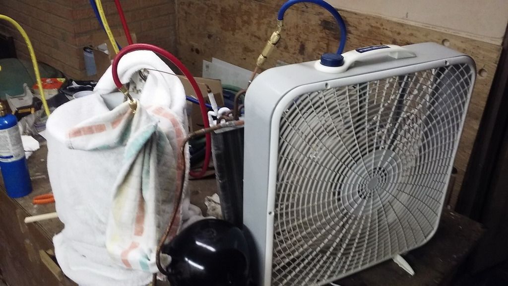 And here's the data 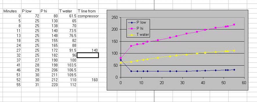 It did a good job of heating the 4 gal of water. I still don't trust my pressure readings. I want to check my gauges against other gauges. I found it interesting how the line temp going into the water keep rising as the water temp rose so that as the water got hotter there was still substantial delta T to drive heat into the water. I didn't realize it would work that way. I have to set this project aside for a few days while I catch up on other obligations. |
|
|
|
|
05-23-16, 12:27 AM
|
#15 |
|
Supreme EcoRenovator
Join Date: Jan 2010
Location: elizabethtown, ky, USA
Posts: 2,428
Thanks: 431
Thanked 619 Times in 517 Posts
|
Ok, a little about measurements. In the primary refrigeration loop, the driving temperatures are the saturation temperatures in the heat exchangers, because the refrigerant condenses or evaporates as close as physically possible to these temperatures. These saturation temps, minus the temps of secondary side temps, determine delta T and heat flow. To directly measure saturation temperature introduces margin for error, so calculating or looking it up is easier and more reliable. You calculate these temps from your high and low side pressure measurements. There are oodles of tables, charts, graphs, and apps like these on the interweb:
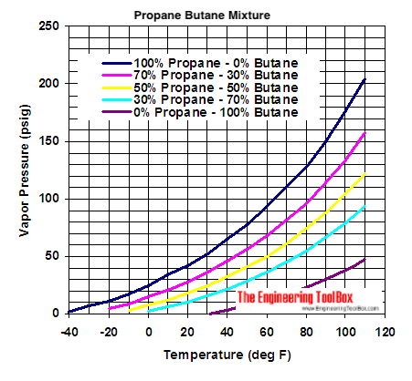 propane-butane mix PT chart CoolApp Library - Mobile Apps for Cooling | Danfoss Danfoss Refrigerant Slider is my go-to app for taking quick measurements on the fly. I believe it does conversions for over 70 different refrigerants. All in the palm of your hand. Super useful. Besides the ambient temps of your heat transfer media (water tank and hx entering air in your case), there are 3 other temps you want to take: compressor discharge, evaporator leaving, and condenser leaving temperatures. Compressor discharge sensing is for safety (thermal high limit) protection. The other two are used with the PT charts to determine evaporator superheating and condenser subcooling. The measured hx leaving temperature is subtracted from the saturation temperature and indicates how much of the respective heat exchanger is picking up (or releasing) sensible heat after the refrigerant has finished changing phase. Sensible heat transfer is many times less efficient than latent heat transfer, but is necessary to ensure your metering device sees only subcooled liquid and your compressor sees only superheated gas. For any given set of environmental conditions, there is an optimum flow rate (AKA mass flow) for maximum BTU's per watt of electricity. With a cap tube, there is only one point where maximum performance is achieved. With an actively controlled expansion valve, the flow rate is determined by measuring the evaporator leaving temperature and pressure. The valve is then set to follow a path of optimized flow rates through a range of conditions. I am leaving a lot of details out of this picture to focus on the measurement aspect. Feel free to ask questions, as understanding the fundamental forces at play will improve your tinkering skills dramatically and improve your chances of success. You will still need to do your own homework, though. |
|
|
|
|
05-24-16, 06:24 AM
|
#16 |
|
Helper EcoRenovator
Join Date: May 2016
Location: SE Wisconsin
Posts: 55
Thanks: 3
Thanked 14 Times in 10 Posts
|
Thanks for following my tinkering and giving that good advise. I do understand every word of it. A year ago much of it would have gone over my head. I've done a lot of reading since I took an interest in this technology. But sometimes while I am actually doing an experiment I don't think fast enough to fully understand what's going on. Taking data and making charts allows me to absorb it afterwards.
For my next test I will make up a condenser from 20 ft of 1/4 copper tube. Put that in the water bucket in place of the alum coil out of the dehumidifier. I need to see if I can also get good performance from a coil like the one that will eventually be used. I now have a small scale and will keep track of the charge weight. I have thermo couple reader and will take temps for getting superheat and subcool. I also have silver solder, it's actually easier to work with than tin/lead solder. |
|
|
|
|
05-24-16, 09:00 AM
|
#17 |
|
Supreme EcoRenovator
Join Date: Jan 2010
Location: elizabethtown, ky, USA
Posts: 2,428
Thanks: 431
Thanked 619 Times in 517 Posts
|
Since you already have your water heater chosen, why not use a similar volume of water in your trials? A Styrofoam 12 can cooler is close, and is like a dollar or 2. You may already have a little playmate cooler lying around somewhere already to use. That way, you can see all about recovery rate, temperature maintenance cycle time, etc. before you rig a hx in your new tank. Every startup cycle, the rig has to build up heat and pressure before any useful heating begins.
With this rig especially, you may not need the unit to start immediately when hot water demand initiates. For larger (longer) flows, the local tank will only see as much cool water is in the supply piping before hot water arrives from the main water heater. In this situation, the local tank will short cycle and waste energy. A delay-on-make timer would be a wise investment if the local tank is connected to the hot water line. If it feeds from the cold water supply, this doesn't matter, as the thermostat will trigger and stay on until the cold water is heated. Last edited by jeff5may; 05-25-16 at 09:27 AM.. |
|
|
|
|
05-25-16, 05:57 PM
|
#18 |
|
Helper EcoRenovator
Join Date: May 2016
Location: SE Wisconsin
Posts: 55
Thanks: 3
Thanked 14 Times in 10 Posts
|
I did a few more tests to see how a different evap coil and charges would affect performance. I removed the aluminum coil from the water bucket and replaced it with about 17/19 feet of 1/4 in copper tube. Everything else the same as previous photos. Here are the results. I don't have a calibrated lab in my basement so keep in mind there is measurement error.
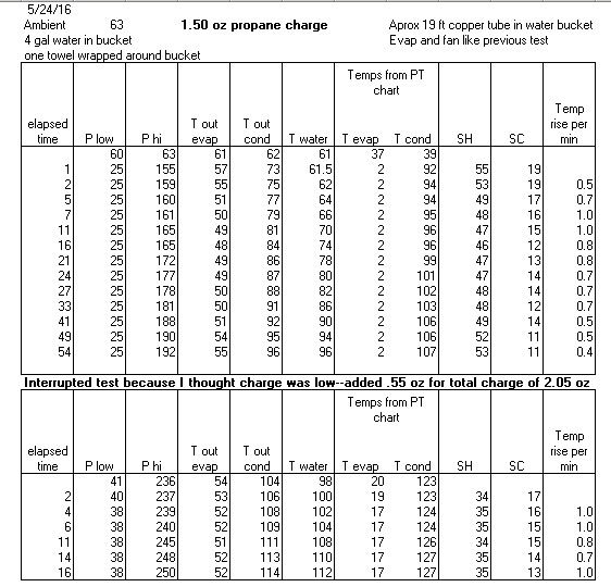 I was surprised that so little propane was required to get fairly good performance. I think it was still a little undercharged, I will work on that after I set up with the actual water heater tank. Then I will also get a watt meter. I am about ready to disassemble my little water heater and add some coils. It seems there are two approaches. The DIY'ers tend to put the coil inside the tank. The commercial ones tend to wrap the coils around the outside of the tank. If I put the coil inside the tank there is a very small chance that it might leak and push gas back into the municipal water system. So I am leaning toward the external approach. And I think the external method would be more of a challenge. |
|
|
|
|
05-30-16, 05:58 PM
|
#19 |
|
Helper EcoRenovator
Join Date: May 2016
Location: SE Wisconsin
Posts: 55
Thanks: 3
Thanked 14 Times in 10 Posts
|
Here's how I attached the heating coil to the tank. First I sanded the tank to remove the scale and get a clean metal surface. Then I tinned that surface. I bought a 20 foot role of 1/4 inch copper tube which came in two spiral layers which I unfolded to make one layer of two connected spirals. I clamped it to the tank with a band clamp.
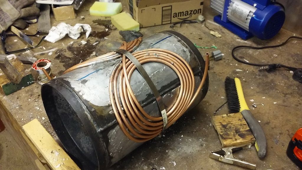 Then I soldered it to the tank. 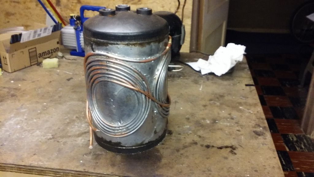 |
|
|
|
|
05-30-16, 06:30 PM
|
#20 |
|
Journeyman EcoRenovator
Join Date: Oct 2011
Location: Cincinnati ohio
Posts: 338
Thanks: 40
Thanked 35 Times in 31 Posts
|
Nice idea.. I'm excited to see how it works
|
|
|
|
 |
| Thread Tools | |
| Display Modes | |
|
|


 Linear Mode

