
|
 06-08-11, 07:44 AM
|
#111 |
|
Helper EcoRenovator
Join Date: Dec 2010
Location: Jamaica
Posts: 59
Thanks: 0
Thanked 0 Times in 0 Posts
|
In regards to the flyback diode which is a very fast recovery diode that is used as a catch or freewheeling diode. Does it have to be a low voltage drop/Schottky diode even thou it is parrallel across the output instead of connecting in series on the positive rail going to the load which in that case you would add a low voltage drop one?
I found one that stated that it is a SUPER-FAST GLASS PASSIVATED RECTIFIER and the details was that it is super-Fast Switching for High Efficiency so I am guessing that this one would be appropriate. Here is the part number so u can check it out if u like and tell me what you think. However it did not stated low voltage drop in the detail thou. Part Number: ER1600CT ER1606CT Datasheet pdf - 16A SUPER-FAST GLASS PASSIVATED RECTIFIER - Won-Top Electronics |

|

|
|
11-11-11, 02:06 PM
|
#112 |
|
Lex Parsimoniae

Join Date: Feb 2009
Location: Woburn, MA
Posts: 4,918
Thanks: 114
Thanked 250 Times in 230 Posts
|
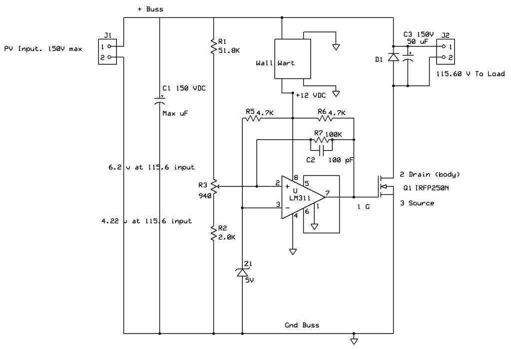
A wall wart will provide the 12V needed for the board, IF it's not raining!!
 Hooked this into the 10 ohm hot water load, but the sun failed to cooperate long enough to find out if there were any wiring mistakes!  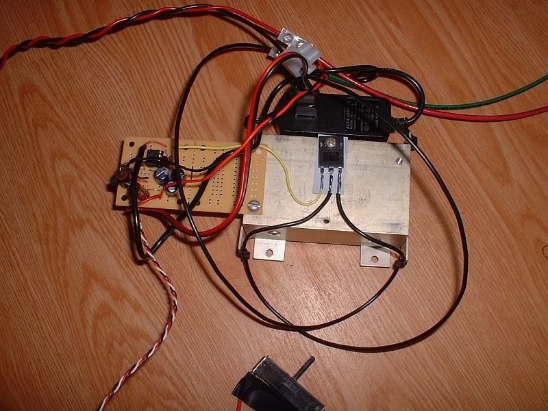 The forecast tomorrow is for partly sunny.. ")
__________________
My hobby is installing & trying to repair mini-splits EPA 608 Type 1 Technician Certification ~ 5 lbs or less.. |
|
|
|
|
11-19-11, 12:47 PM
|
#113 |
|
Lex Parsimoniae
Join Date: Feb 2009
Location: Woburn, MA
Posts: 4,918
Thanks: 114
Thanked 250 Times in 230 Posts
|
When I was testing the other day, (when it was cloudy) something went wrong with the circuit,
and I think maybe the FET shorted? or somehow fed high voltage back into pin 7 of the LM311 chip. Not sure. The chip started smoking pretty fast. By the time I caught on, it had melted right into the socket! One hour of careful soldering work down the tube! So, now I'm thinking of using a power switch that will be completely isolated from the PV's high voltage. Solid State Relay SSR 5-220V DC, 40A + Heat Sink | eBay There isn't a lot of difference between a DC SSR & the AC SSR. I should be able to connect the PV & load to the DC SSR (as shown below) and drive the input circuit with a square-wave. I will also connect a 3500 uF (150vdc) cap across the PV lines. During bright sunlight, I can easily find an optimum frequency/duty-cycle, that will transfer maximum power into the 10 ohm load. But, I'm not sure how well a fixed frequency would work during less-than optimal sun light conditions. My best guess is, if I can get the source-load mis-match cured during bright sunlight, there is a good chance that lower sunlight conditions will also see an improved power transfer. When the parts come in, I'll test the simplified version of PPT.. 
__________________
My hobby is installing & trying to repair mini-splits EPA 608 Type 1 Technician Certification ~ 5 lbs or less.. |
|
|
|
|
12-02-11, 06:55 AM
|
#114 |
|
Dan_LASER

Join Date: Dec 2011
Location: Romania
Posts: 17
Thanks: 0
Thanked 0 Times in 0 Posts
 |
Hello
My name is Daniel and I'm from Europe Romania Mr. Xringer Got a request for you if you can help me with two pictures of the solar tracking circuit one front and one back circuit please help me If you do not mind I try to build a solar tracker circuit I the pictures help me build one Thanks look forward to your response |
|
|
|
|
05-19-12, 10:29 PM
|
#115 | |
|
Lurking Renovator
Join Date: May 2012
Location: Oldsmar, Fl
Posts: 3
Thanks: 3
Thanked 0 Times in 0 Posts
|
Quote:
I'm a little confused on if this will or will not help me here in Florida so I thought I would run some tests play with some circuits and generally just try to learn something. I was wondering if you had any progress, have you tested this yet? Also I'm still reading up on what MPPT does with the panels, its my understanding that having the panel 'see' a particular voltage will have it be more or less efficient, this doesn't sound right to me. I'm still reading up on exactly what that does though. I've got some spare PIC's laying around, I'm going to see if I cant use those for some sort of basic algorithm as well as a timing circuit for a few peek performance under various conditions. My biggest goal is to be able to have mix matched solar panels provide the best they can. I would really like to be able to count a 20W 200W and 130W as 350W vs somewhere around 60W with a soon to be blown up 20W panel. Thanks for any books/references/links/etc you may point me to  |
|
|
|
|
|
05-20-12, 08:17 AM
|
#116 |
|
Lex Parsimoniae
Join Date: Feb 2009
Location: Woburn, MA
Posts: 4,918
Thanks: 114
Thanked 250 Times in 230 Posts
|
If you read and understood the information given in the link Build this simple Mini Maximiser
on the first post, you know the idea here is to allow the panel voltage to get up to it's optimum/MPP voltage. So your goal of 'mix matched solar panels' working together isn't going to be achievable, if those panels supply a different MPP voltage. That would be like trying to put a 12v battery in parallel with a 9v battery. The 12v is going to dump power into the 9v. Over-charging-heating, melting? There is a solution to mixed panels, and it's the GTI. (Like the Enphase). Since the GTI (grid tied inverter) takes the DC from it's PV and turns that power into AC power. Compatibility between different panels is achieved at AC levels.. Hence the popularity of Enphase. It allows one to use what ever PV can supply power within it's input voltage range.. The Powejack GTIs from Ebay work about the same way, but are illegal in the USA and tend to smoke at times..  This guy is using them successfully. My last experiment used a square wave into a DC SSR (solid state relay) and didn't end well. I think the SSR used wasn't as rugged as needed for the job.. What I have done, is add about 6 ohms of series resistance to my 10 ohm load. Now, when the sun is right, I can get much better efficiency (60 to 80%). Because the load is better matched to the MPP voltage of the PV.. Anyways, I'm not sure that I want to continue with this DIY MPPT project, since I want to try using a heat pump to make my hot water. In that case, that 800w of PV might be used to drive my heat pump..
__________________
My hobby is installing & trying to repair mini-splits EPA 608 Type 1 Technician Certification ~ 5 lbs or less.. |
|
|
|
| The Following User Says Thank You to Xringer For This Useful Post: | Simy (05-21-12) |
|
05-21-12, 06:25 PM
|
#117 |
|
Lurking Renovator
Join Date: May 2012
Location: Oldsmar, Fl
Posts: 3
Thanks: 3
Thanked 0 Times in 0 Posts
|
Xringer,
I appreciate your link's and information. I'm still a bit confused. I've been reading from all over the web.... I've actually got 90% of the parts I need to make a PWM circuit, or an MPPT circuit around the house. I found a broken speed controller for an RC helicopter. Its got a few burnt out mosfets but the rest of the circuit seems fine so I'll test it with that. I've also got a few spare PIC12F1822's that I plan to program. What I'm thinking is quite simple, measure the input voltage of the capacitor once it starts to rise past a specific amount dump it to a second capacitor which is wired in series/parallel with other solar panels. Then check for the voltage drop, if the volts drop to low, disconnect. Rinse & repeat. With this chip I believe I can do AC or DC output but won't I take an energy hit? My thinking is with a fairly simple, stupid, and flexible per panel chip, and wiring the panels up for higher voltages the line losses won't hurt so much. My panels will be located 20-50' away from the batteries. I figure with proper insulating I can run 1 cable at around 60-100 volts into a buck converter that can charge the batteries. This would remove most of the issues I see when I look around. I assume that this is all possible to do with a second capacitor being the load that the PWM/MPPT circuit dumps into. I remember seeing a circuit where capacitors are charged in parallel and discharged in series to raise the voltage (at the expense of current) Would this not work or do I need to make sure the output side is all the same voltage? The other issue this would eliminate is allow one panel to be broken/shaded without dragging down the entire system which is something I'm quite interested in because I can get more panels mounted, but some would be partially shaded in the morning/night. I wan't to get the most power out of my cells as I can and seeing as it looks like its going to take a few months before I can purchase these panels I can work out all these pesky little details before hand. From what I've been able to read the main reason an MPPT gets more power is because the PWM type circuits don't do DC-DC conversion and really only look at the battery side for the voltage and cut off the solar panel before it can reach its maximum voltage. The MPPT, looks at the panel and at the battery. but from what I've seen there doesn't seem to be that much of a difference between a max of 15V and a max of say 17V. The panels peak voltage +/- a few volts shouldn't dramatically impact efficiency a simple PWM type circuit would be fine for that. One chart shows that an MPPT circuit operates at say 15-17V, while a PWM would be at 13-15V. The amps more or less stay the same, so assuming its a 100 watt panel, your loosing about 11-12 watts from 15 to 17V I think I may need to start another thread at some point... if I can do what I'd like to do. I'm more or less thinking per panel DC-DC PWM converter with some 'smart' tricks (so its midway between MPPT and dumb PWM) and then a high voltage input to pack voltage charger. Eliminating line losses as much as possible and like I said previously, allowing mix matched panels/partially shaded panels, etc. My goal is to have a system as resilient to failure and poor installation as possible I'd prefer a system that can be deployed in less then ideal situations and still yield near the maximum benefit. I'm just not sure if this is the way to start or not. |
|
|
|
|
05-21-12, 08:05 PM
|
#118 |
|
Lex Parsimoniae
Join Date: Feb 2009
Location: Woburn, MA
Posts: 4,918
Thanks: 114
Thanked 250 Times in 230 Posts
|
One of the problems that I have with my battery back-up system is wasted power.
But it's not because I'm charging my battery bank with a PWM charge controller, it's because I'm not using the PV, AFTER the bank is charged. My other dilemma is what to do with my stored power.. I can't use very much off the batteries, since I don't want to end up with a flat bank, when I really need it. (During a grid failure). So, please tell me what you plan to do with the power. Then, I can have some idea of what kind of system you should design. Or, do you just want to experiment on a small scale to see what can be accomplished with by simple MPP control circuits, vs PWM??
__________________
My hobby is installing & trying to repair mini-splits EPA 608 Type 1 Technician Certification ~ 5 lbs or less.. |
|
|
|
|
05-21-12, 11:16 PM
|
#119 |
|
Lurking Renovator
Join Date: May 2012
Location: Oldsmar, Fl
Posts: 3
Thanks: 3
Thanked 0 Times in 0 Posts
|
There is the long and the short term. Short term I want to get a handle on how it works so I'm going small scale, and playing with electronics a bit. If the PWM charge controllers can be boosted by as much as 20-30% in sub-optimal conditions then by all means I'm game to try and make a dead simple and cheap MPPT. I'm not so sure that will help me too much however as I'm in Florida and the apparent gain is from when its colder out, but I figure by mixing the systems like I describe above I can use mix matched panels which is something I may very well be doing anyway.
Long term is I want to buy some used panels and see if I can't very cheaply get a room off the grid, then another room, then another. Every year I don't buy power is about another $1,000-$1,200 in my pocket. =D Here is a quick little sketch of what I want to do:  This is also why people pay me to NOT draw them at the county fair  Last edited by Simy; 05-22-12 at 12:04 AM.. |
|
|
|
|
05-22-12, 06:54 PM
|
#120 |
|
Lex Parsimoniae
Join Date: Feb 2009
Location: Woburn, MA
Posts: 4,918
Thanks: 114
Thanked 250 Times in 230 Posts
|
I think a series setup like that is going to limit the max current, to the current produced by the weakest panel..
Look at it like a 3 cell flashlight. Two of the batteries are brand new, and one is ready for recycling. The light bulb is going to perform poorly.. If one of your panels becomes shaded, it brings down the system.. If you used the MPPT circuits in parallel, with each using a boost circuit to bring their output voltage to the same level (all outputs to 17vdc?), then they will work together providing max power from their panels.. These two setups can put the same power into a load.. (the resistance of the series load would need to be 4x the parallel load).  But, if one of the series cells gets weak, the series output is kaput.. This is not true of the parallel.. That's the beauty of the parallel output of Enphase GTI.. Every inverter puts out 230vac.. (all in phase with each other)..
__________________
My hobby is installing & trying to repair mini-splits EPA 608 Type 1 Technician Certification ~ 5 lbs or less.. |
|
|
|
| The Following User Says Thank You to Xringer For This Useful Post: | Simy (05-22-12) |
 |
|
|


 Linear Mode

