
|
 06-03-10, 11:46 AM
|
#71 |
|
Apprentice EcoRenovator

Join Date: Dec 2008
Location: mid michigan
Posts: 191
Thanks: 0
Thanked 0 Times in 0 Posts
|
Wow that's a beast compared to mine
 . . Is that a wood burning side on the right? Have you ever used wood in yours? I wonder how much loss escapes from that side when you aren't using wood. Or does it have a totally seperate water circuit? |

|

|
|
06-03-10, 12:27 PM
|
#72 |
|
Lex Parsimoniae

Join Date: Feb 2009
Location: Woburn, MA
Posts: 4,918
Thanks: 114
Thanked 250 Times in 230 Posts
|
Wood or coal. I have used both (in the distant past).
The warm air loss up the chimney is one of the main problems with this type of boiler. It might be less when using wood, as compared to oil.. Here's the manual link Woodboilers.com » Discontinued Boiler Infor My model is the OT-35 and it's a bit over-sized for my house. |
|
|
|
|
06-04-10, 03:39 PM
|
#73 |
|
Lex Parsimoniae
Join Date: Feb 2009
Location: Woburn, MA
Posts: 4,918
Thanks: 114
Thanked 250 Times in 230 Posts
|
Looks like I'll be keeping these..
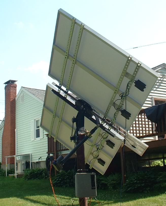 I drilled 16 holes and installed 16 1/4-20 bolts, 1.5"x1.5x0.25" spacers, and 16 SuperStrut 1/4-20 inserts. Hopefully, these two extra struts will hold up to the weather.. |
|
|
|
|
06-05-10, 02:43 PM
|
#74 |
|
Lex Parsimoniae
Join Date: Feb 2009
Location: Woburn, MA
Posts: 4,918
Thanks: 114
Thanked 250 Times in 230 Posts
|
Finished building the 10 Ohm resistor today and it shows exactly 10.0 Ohms
on both of my good meters. The weather is warm. 83 degrees and humid. At 14:20 eastern, there was light high clouds. The backside of the panels was 134 degrees F. Here's the test setup, on the base of the mount. 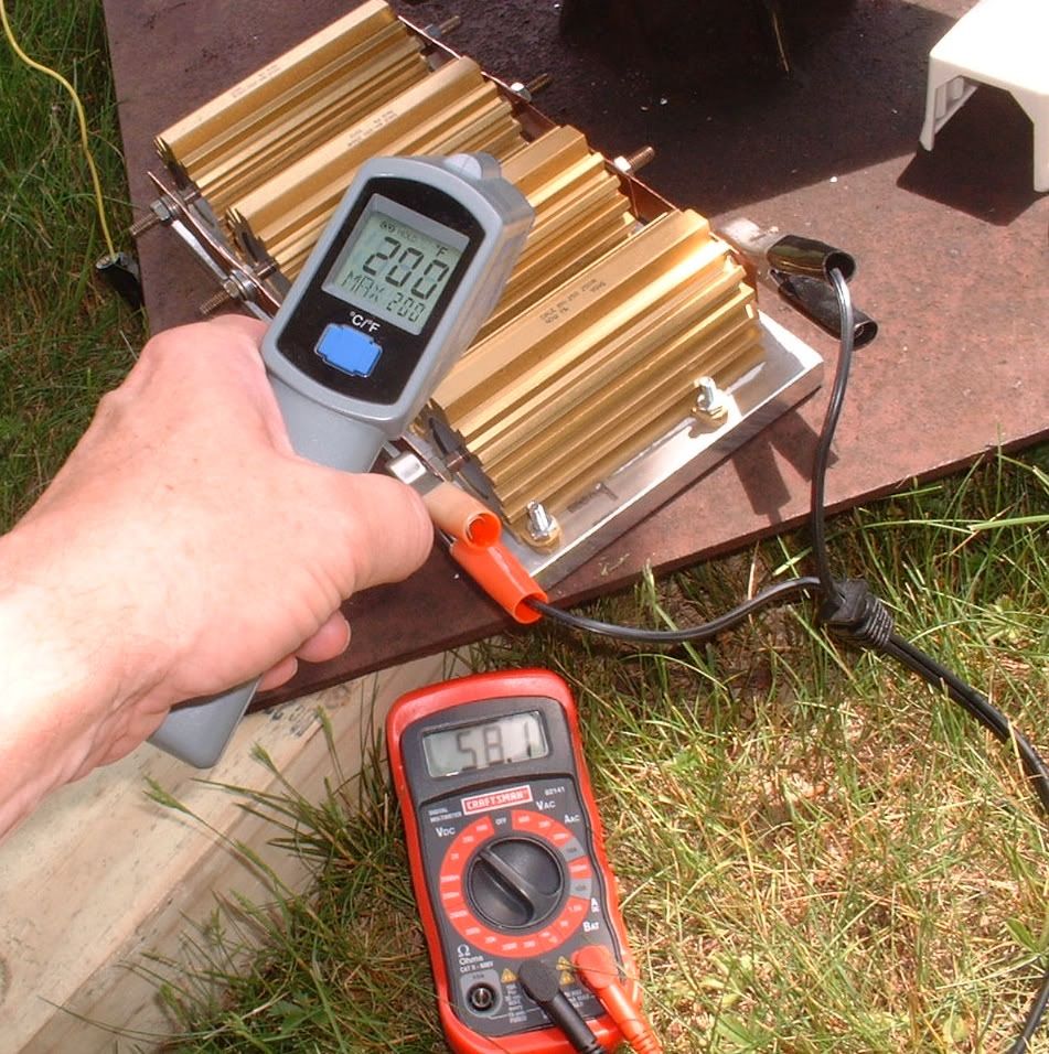 This pic was taken when the clouds were thick.. Max voltage into the load was 65.5v, and average was 63 to 64.5 65.5v / 10 ohm = 6.55 amps or 429 watts of heating.. (1,464 BTUh) The less than idea conditions cost us about 71 watts (242 BTUh). (That 71 watts off the array's rating of 500 watts). If we get some clear skies during the next few days, I'll do another test. Hopefully, when I install the load on the boiler, my cable won't have high losses. In any event, the power cable's resistance is going to add to the 10.0 ohms. That might allow a bit higher voltage from the panel..?. Moving the power-point back from the downside of the knee.?. If that makes the panel power a bit greater, it might over-come the power line loss, and present a high voltage at the load.. Max temperature of the heater plate was 266 degs F. The heatsink compound was bubbling out, so I shut it off. It heated the rusty steel plate under the heater (in one corner) to 143 degs F. (The other side in the shade was at 93 degs F). If I can get a good thermal bond with the boiler, the max temperature shouldn't get so high.. After all, it will be trying to heat a lot of steel and 76 gallons of water.. Last edited by Xringer; 06-05-10 at 02:46 PM.. Reason: typos galore |
|
|
|
|
06-05-10, 07:02 PM
|
#75 |
|
Apprentice EcoRenovator
Join Date: Dec 2008
Location: mid michigan
Posts: 191
Thanks: 0
Thanked 0 Times in 0 Posts
|
That's pretty cool... I mean hot!
What kind of cable have you decided to use to bring the power in? |
|
|
|
|
06-05-10, 07:48 PM
|
#76 |
|
Administrator

Join Date: Aug 2008
Location: Germantown, WI
Posts: 5,525
Thanks: 1,162
Thanked 374 Times in 305 Posts
|
Very interesting. Are you planning on mounting the plate to the boiler?
__________________
Current project - To view links or images in signatures your post count must be 0 or greater. You currently have 0 posts. To view links or images in signatures your post count must be 0 or greater. You currently have 0 posts. & To view links or images in signatures your post count must be 0 or greater. You currently have 0 posts. |
|
|
|
|
06-05-10, 10:21 PM
|
#77 | ||
|
Lex Parsimoniae
Join Date: Feb 2009
Location: Woburn, MA
Posts: 4,918
Thanks: 114
Thanked 250 Times in 230 Posts
|
Quote:
I'm thinking of using RG-8 type coax. Not sure how well it will work, but that's what experimenting is all about.  Quote:
and it might do a good job of holding the aluminum hot plate to the steel boiler. J-B Weld Company - J-B WELD Product Information 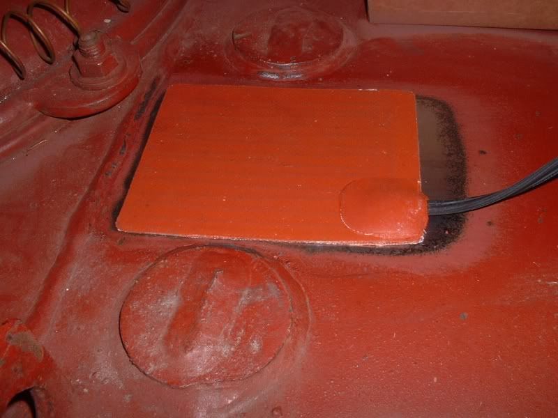 I'm going to pull up my old 250w heating pad and then sand down the area (6"x11") to the right of it, so the new hot plate will have good contact with the steel. I plan to install a metal cover/lid over the resistors. Then, I will cover the outside of the 'lid' with foil backed FG insulation. I need the wiring inside the box to withstand 300 to 400 degs F, so maybe I'll need to start looking inside of some toaster ovens. ") Last edited by Xringer; 06-05-10 at 10:49 PM.. |
||
|
|
|
|
06-07-10, 01:02 PM
|
#78 |
|
Lex Parsimoniae
Join Date: Feb 2009
Location: Woburn, MA
Posts: 4,918
Thanks: 114
Thanked 250 Times in 230 Posts
|
Using about 100 feet RG-8
At the mount, I see about 65 to 66 volts. Inside at the load, it's 62.3 to 63 volts. I seem to be using 3 valuable volts.. So, right now the load is dissipating 63 / 10 = 6.3 Amps. About 397 watts of heat. The last test, using a cheap 120vac 100' extension cord was 32 watts better..  I'll have to cut the coax shorter and try again.. Edit: Not much to cut off, just about 16 feet. Saw a peak voltage of 66.6v and the average was about 66v. Indoors at the load, it was 63.5v, so it's down about 2.5 volts on average. 63.5 / 10 =6.35 Amps, or about 403 watts of heat. Last edited by Xringer; 06-07-10 at 06:59 PM.. Reason: Had a need to edit |
|
|
|
|
06-09-10, 07:17 AM
|
#79 |
|
Lex Parsimoniae
Join Date: Feb 2009
Location: Woburn, MA
Posts: 4,918
Thanks: 114
Thanked 250 Times in 230 Posts
|
Got the hotplate installed last night. After a lot of sanding and mixing epoxy..
Now here comes the bad weather.. NWS - National Mosaic Enhanced Radar Image: Full Resolution Loop It's 8AM and the storm clouds are rolling in.. So, we might have to turn the oil back on soon..  After the J-B Weld had set for 6 hours, I turned on the oil (at midnight) and moved the boiler temp up from 90 to about 125 degrees, for a bit faster cure. I do have some voids on the some of the edges, but I think the plate is pretty well bonded to the boiler. (At least 90%). The hot plate now has an aluminum top cover (Heat Shield) that has 1" of FG insulation on all outer surfaces. (No pics yet, I didn't want to epoxy my old camera in there)..  I hope to keep any 'killer' heat inside the cover, so we get a good 180-250 degree hot-spot under the plate.. (WHEN the sun comes out)! If it comes out, the heater is ON and the tracker is ready to track.. ~~~ Edit: 13:53 06/09/2010 08:00 125 degrees F 09:20 122 F (morning water use). 09:30, we left for Candle-pin bowling.. 12:45 135 F 13:39 139 F (Solid overcast now).. 139 - 122 = 17 degree gain! That's not a lot of direct sunshine, if it wasn't so cloudy today! It's been a pretty hazy day so far and there's a lot of passing clouds.. So far, the system seems to be working as hoped. Last edited by Xringer; 06-09-10 at 01:00 PM.. Reason: 17 degree Heat gain! |
|
|
|
|
06-10-10, 08:03 PM
|
#80 |
|
Lex Parsimoniae
Join Date: Feb 2009
Location: Woburn, MA
Posts: 4,918
Thanks: 114
Thanked 250 Times in 230 Posts
|
One goal of this experiment is to see if it's possible to use RG-8U type coax as a PV power transmission line.
The reason for using coax, is mostly the cost. RG-8U is a low cost cable. It used to be widely available on the surplus market. And, I have a couple hundred feet that's in pretty good shape. The center pins of N connectors are normally coated with gold, which is a very good conductor of electrons. It can easily handle large mounts of RF power and I have used it to carry DC power (for short distances) over 1KV at 0.5 to 1.0 Amp. Another reason for using coax is safety. Since the outer shield of the coax is ground (common) or negative in my case, it's prefect for grounding. (I have an 8 foot ground copper clad ground rod to be installed). The large N-connector (upper right) is the PV power output port. N-connectors have internal rubber gaskets and are very resistant to water. The 'N' female and the ground lug(sliver plated) are mounted tightly on a copper plate. 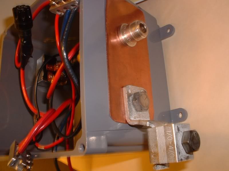 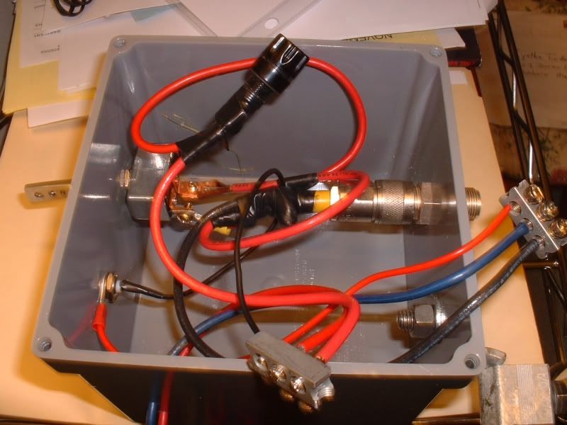 Upper left is the PV off-on switch. Lower left is a female BNC connector for test measurements. Note: The BNC test port wires have reversed colors. The 10A fuse is located top center. The Blue negative - PV wire comes in from the bottom and goes into the center hole of the 3 hole terminal (right side). The Black wire (right hole) connects back to the coax cable ground-shield (outer copper braid). The small red '-' wire is the ground back to the BNC test port. The '+' three-hole terminal (bottom center), center hole comes from the Positive '+' PV line. The large red wire in the right side hole connects to the fuse, then is switched into the center pin of the coax cable.. The small '+' black wire on the left, goes back to the center pin of the BNC connector. Both of the 3-hole terminal blocks will be re-tightened and taped up before the waterproof cover is installed. All 6 of the holes will have to be water-proofed before long term testing. |
|
|
|
 |
| Tags |
| electric, solar, tracker |
| Thread Tools | |
| Display Modes | |
|
|


 Linear Mode

