
|
 01-13-13, 05:21 PM
|
#331 | |
|
Helper EcoRenovator
Join Date: Oct 2012
Location: Beuningen (Gld), the Netherlands
Posts: 64
Thanks: 4
Thanked 19 Times in 16 Posts
|
Quote:
I'll connect the HRV to the existing ductwork so that toilet- and bathroom air will pass through the HRV. For this I made it so that when it's colder outside more air will be extracted in total than is inserted into the livingroom. (When it is not colder then several windows will be open, enough ventilation) Our livingspace is the warm area, upstairs can be colder. The warm area is well sealed, floor insulation is so-so, which will be my next project. The goal for the warm living area is balanced ventilation with HRV. Upstairs will have some negative pressure, colder fresh air will trickle in, especially via the attic which is actually a useable room (In the Netherlands an attic is livingspace or a storageroom, we insulate the roof instead of covering the floor with a foot of cellulose) So the HRV will take over from the whole house extraction fan. That single fan (anno 1984) uses more electricity than the 2 in the HRV together, 20,- gain per year on that. So far I didn't mention the bathroom, it's upstairs and the sketch a few posts above only covers the groundfloor. I did include it in my plans though, it is a place that needs ventilation after all, need to remove the moist from taking a shower, and can recover heat from that. |
|

|

|
|
01-14-13, 02:41 AM
|
#332 |
|
Helper EcoRenovator
Join Date: Dec 2012
Location: Venice, Italy
Posts: 89
Thanks: 15
Thanked 41 Times in 19 Posts
|
Here's what I'm planning to do for the ducting.
I live in a two-floor house (total area 90 sqm), ground floor is another property, on the first floor I have the entrance, an open space with the kitchen and a slightly separate living room, a bathroom and the stairs that lead to the attic. There I have a small corridor, another bathroom, a studio and two bedrooms. Behind all this there is a small place (25 sqm) used as a closet. I will install the HRV there as I can easily reach every room using short distance ducts (max is 5 mt long). I will plug the main inlet and outlet to the outside via the roof right above the machine (the drawing is quite schematic, in and out ducts will be much more distant from each other). On the first floor I will have fresh air in at the living room while taken the stale air from the kitchen area and the bathroom. On the attic I'll plug the fresh air in the bedrooms and take it back from the bathroom and the stairs arrival (in that way I'll get some of the kitchen odors that inevitably go upstairs + max hot inside air). I think it's quite balanced like that. The only problem is that I'll have to make three 120mm diameter holes to the attic towards the first floor, that's 45 cm thick!  |
|
|
|
|
01-14-13, 09:55 AM
|
#333 | ||
|
Super Moderator

Join Date: May 2009
Location: Warsaw, Poland
Posts: 961
Thanks: 188
Thanked 110 Times in 86 Posts
|
Quote:
Putting smaller HXs ahead of the main recuperator will increase the efficiency of the whole setup, like having a larger recup. Quote:
__________________
Ecorenovation - the bottomless piggy bank that tries to tame the energy hog. |
||
|
|
|
|
01-14-13, 11:18 AM
|
#334 | |
|
Helper EcoRenovator
Join Date: Dec 2012
Location: Venice, Italy
Posts: 89
Thanks: 15
Thanked 41 Times in 19 Posts
|
Quote:
First some dew may occur to the exhausting duct, so I'll have to put another condensation pipe. Second the heat exchanged by those ducts will only affect the destination rooms and not the whole system. Sincerely I have serious doubts about the effectiveness of this solution. But I am speaking as a non-expert, so maybe I'm wrong. Speaking about the aforementioned ductwork I was thinking of another improvement: In the first floor I have the internal AC unit (Daikin dual split 18000Btu Inverter) placed between the stairs and the bathroom (AC1 in the drawing). In the summertime I could deviate the fresh air supply right above the unit so that the incoming air gets immediately chilled and distributed with major speed by the fans. While above the kitchen I could add some more recessed intake points in order to catch all that precious heat generated by cooking in winter time ...  What do you guys think about it?  Last edited by kostas; 01-17-13 at 03:30 AM.. Reason: image placement |
|
|
|
|
|
01-15-13, 04:42 AM
|
#335 | |
|
Helper EcoRenovator
Join Date: Dec 2012
Location: Venice, Italy
Posts: 89
Thanks: 15
Thanked 41 Times in 19 Posts
|
Having a second thought of it, conveying the FAI duct to the AC in the summer seems to be quite mandatory...
Quote:
BTW, the guy's blog has an interesting and useful duct construction guide here: Excess Air: Rules of Duct Design, Why? |
|
|
|
|
|
01-15-13, 09:20 AM
|
#336 | ||
|
Super Moderator
Join Date: May 2009
Location: Warsaw, Poland
Posts: 961
Thanks: 188
Thanked 110 Times in 86 Posts
|
Quote:
Quote:
__________________
Ecorenovation - the bottomless piggy bank that tries to tame the energy hog. |
||
|
|
|
|
01-15-13, 10:13 AM
|
#337 |
|
Helper EcoRenovator
Join Date: Dec 2012
Location: Venice, Italy
Posts: 89
Thanks: 15
Thanked 41 Times in 19 Posts
|
Yes, you could be right about it.
But my guess is that you'll need something more that just two adjacent ducts to exchange some serious amount of heat. Theoretically speaking you could put a number of some CPU heat coolers on both channels (side to side) to enable heat transfer. Something like this without the peltier chip: 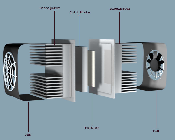 But then, you could always built a more efficient HX by adding some more PP sheets!..  |
|
|
|
|
01-15-13, 12:17 PM
|
#338 | |
|
Supreme EcoRenovator

Join Date: Mar 2009
Location: Portland, OR
Posts: 4,004
Thanks: 303
Thanked 723 Times in 534 Posts
|
Quote:
I would like to see how you are going about it. -AC
__________________
I'm not an HVAC technician. In fact, I'm barely even a hacker... |
|
|
|
|
|
01-15-13, 04:19 PM
|
#339 | |
|
Super Moderator
Join Date: May 2009
Location: Warsaw, Poland
Posts: 961
Thanks: 188
Thanked 110 Times in 86 Posts
|
Quote:
Since there are many different temperatures to keep track of, I'll use a drawing to explain which is where: So there are two heat exchangers: All of the air goes through HX1, but only part goes through HX2. Fin: Fresh air in, Out1: Fresh air leaving HX1, RF1: Fresh air entering Room1, temperature equal to Out1, In2: Fresh air entering HX2 temperature equal to Out1, RF2: Fresh air exiting HX2 into Room2, RS2: Stale air entering HX2 from Room2, Out2: Stale air exiting HX2, RS1: Stale air from Room1, In1: Stale air entering HX1, temperature is a weighted average of Out2 and RS1 Sout: Stale air exiting HX1 to outdoors. My assumptions:
So, since Out1=16°C, then this is the temp of the fresh air going to Room1 (RF1) and going into HX2 (In2). HX2 recovers 80% of the heat, and the temp difference of its two inputs RS2 and In2 is 20-16=4°C, then RF2=In2+0.8*4°C=19.2°C, and Out2=16.8°C. In1 is the average of Out2 and RS1, since equal amounts of HX1's air go through HX2 and go to Room1. So In1=(16.8+20)/2=18.4°C. OK, now we are back at the first step (where we temporarily assumed that In1=20°C). Now we do everything over again starting with In1=18.4°C. This will change most of the numbers and after a few steps we get yet another value for In1. With each iteration the changes become smaller, so 3-4 steps are enough. I did this again assuming that the Room1 and HX2 split HX1's air not equally, but 1:2 (ie HX2 gets twice as much air as Room1). The only real variation is that In1=(RS1+2*Out2)/3 instead of a regular average. As I mentioned earlier, these calculations were meant to be quick and dirty. There may be a better way to do it, but I am not John von Neumann to sum up infinite series Just an estimation was enough in this case.Anyone who wants to do this in more detail should plug in his own numbers: each HX may have a different efficiency, each room may have a different temperature, etc. Moisture in the air will also skew the results. Have fun!
__________________
Ecorenovation - the bottomless piggy bank that tries to tame the energy hog. |
|
|
|
|
|
01-19-13, 05:10 PM
|
#340 |
|
Helper EcoRenovator
Join Date: Dec 2011
Location: tigard, oregon
Posts: 42
Thanks: 0
Thanked 4 Times in 4 Posts
|
I tried the computer heat sink method.
Problem is that the thing is designed to get rid of about 100W with a temperature differential > 60C. The heat pipe temperature differential was relatively small, but, at low temperature differentials, it boils down to coupling to the air with tiny delta-T. I didn't save the test data because it wasn't even close to feasible in my context. I don't think there's anything wrong with the concept if you can make it BIG enough. In order to get more than 50% efficiency, you need a temperature gradient over the transfer path. That's gonna require multiple heatsinks and heatpipes in series. I tried to solve that problem with a bunch of butane cylinders poked thru two adjacent ducts. Same problem. Heat pipes work fine, just need a way to get the heat out of 'em into the air. I had some emotional issues with my HRV being a bomb. Would work great for water to water heat transfer. I thought about spot welding some fins, but decided a live butane tank wasn't the best choice for welding. |
|
|
|
 |
| Tags |
| erv, heat recovery, hrv |
|
|


 Linear Mode

