
|
 02-13-12, 12:08 AM
|
#1 |
|
Apprentice EcoRenovator
Join Date: Dec 2010
Location: Western Australia
Posts: 148
Thanks: 1
Thanked 48 Times in 34 Posts
|
I don't want to clutter up the real information threads in here, so I've started one just so I can put up misc stuff I'm working on that might be of interest to others, and to show some tools I'm currently using.
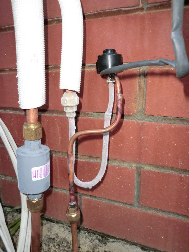
This brazing monster is a TurboTorch TH1 snake torch with the head swapped for an STK-11 double burner. It also has a stainless steel heat deflector/reflector that I use to stop setting fire to stuff and help heat the tube quicker if I can get around it. I bought the STK-11 a little while ago, but it is pretty ungainly having to wield the bottle around, so when I spotted the TH1 snake kit it was a natural fit. This will let me braze up a 5/8" line in about 10 seconds. It's amazingly hot and comfortably blew a hole in a 3/8" tube last night. I've used it crawling around in the roof and managed not to set fire to anything. 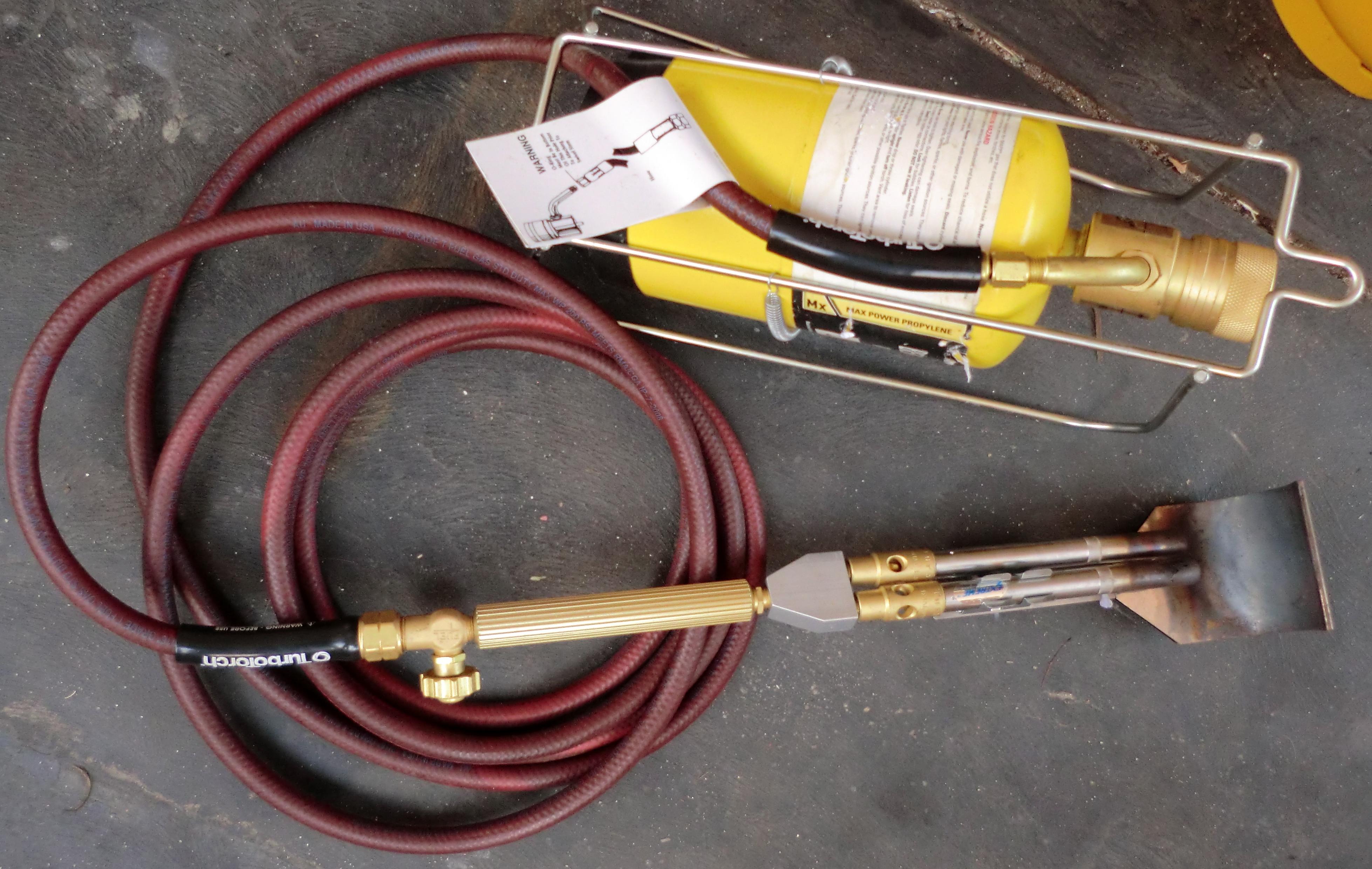 Those heat shields are worth their weight in gold. It literally halves my brazing time. If you can find one, buy it. Now, my little experiment. Currently I have a 7KW Ducted heat pump installed. This has orifice piston expansion devices. Basically a bit of brass that seats and forces the refrigerant through an orifice when flowing one way, and unseats and presents no restriction when flowing the other. With one of these on each coil, it becomes easy to swap the roles of evaporator and condenser when the reversing valve flips. Now, I inherited this heat pump from a Hospital, where it was cooling a pair of operating theatres. They removed it because it was unable to keep control of the humidity. Having installed it at home, I now see why. On high ambient days (>35C - which is quite a bit of summer here), the head pressure causes evaporator overfeeding, which means the SST is about 10-12C. This is not cool enough to drop the air temp past the dew point, and thus you get cool but wet air. A while ago I salvaged an old multi-head Daikin split unit. It had 3 EEV's which I pulled out and put aside for another time. 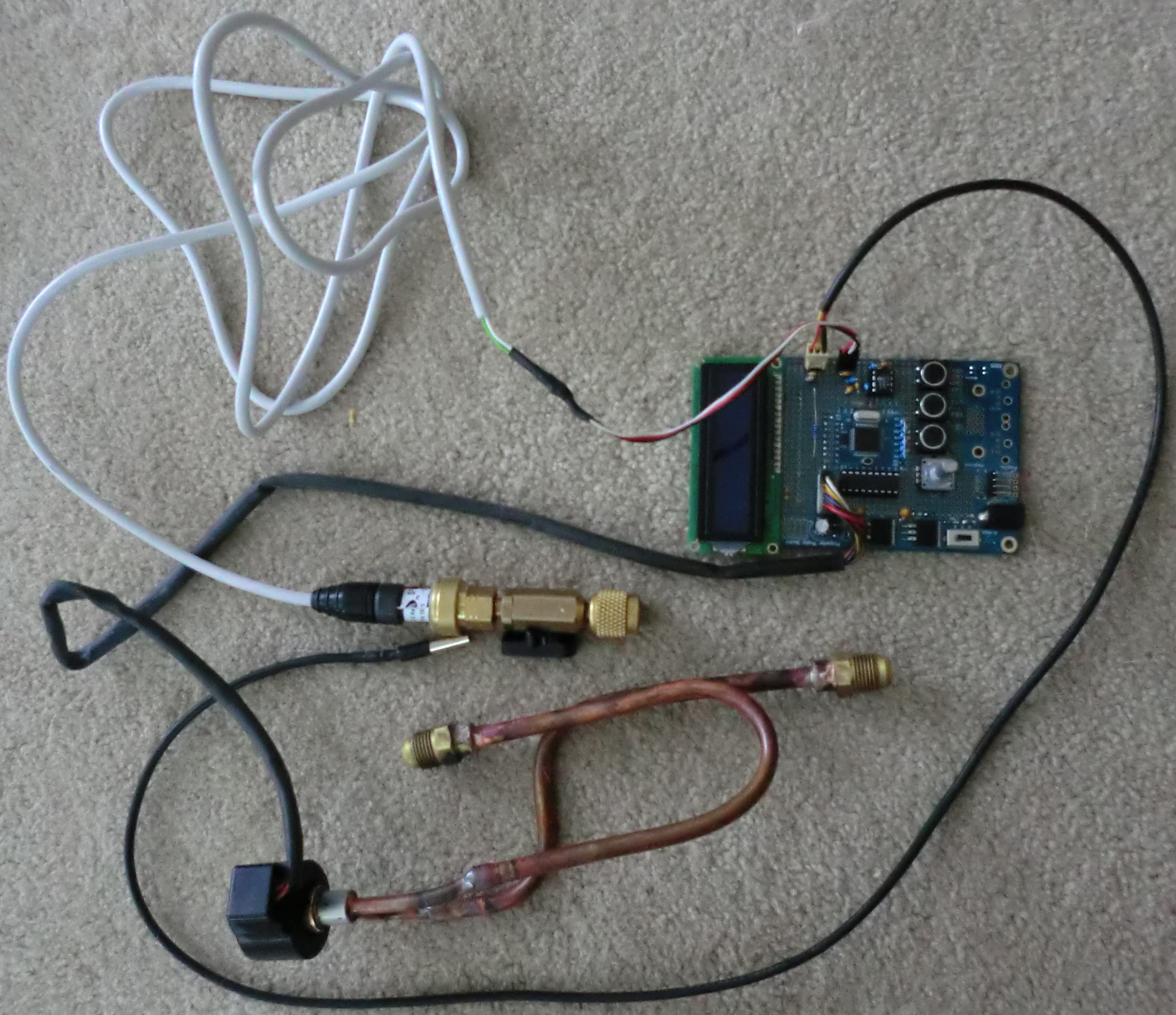 I've finally got off my backside and built a controller for one of them. When I installed the heat pump, I put a second 3/8" flare filter/drier in the liquid line. Conveniently this means I can insert the EEV in its place, and simply pop the orifice out of the evaporator, thus I brazed up this little bit of pipework with some 3/8" males on the end that fits where the drier is now. I've built the R290 PT Chart into the software, and that pressure sensor is a Carel ratiometric. The LCD gives me the saturated suction temperature (SST), and also the real temperature from the little silver probe (A Dallas DS18B20 digital unit) so I can instantly see the real-time evaporator temperature and superheat. The rotary encoder on the panel allows me full manual control over the EEV, so I can twiddle the knob and observe the effects. I've set it up this way as I don't really know : A) What I'm doing B) If the valve is going to flow enough refrigerant for this unit I can manually control things until I get a feel for how it's going to work, before I go and either replace the valve for a bigger one (I have one I scrapped off a 15KW unit here somewhere), or write a control algorithm to let it do its own thing. I've run the sensor for the full range (-14.7-150PSI) against my Testo 550 and the calculated temperature is always within half a degree C, so the software is in the ballpark. Now I just need some time to pump down the unit, swap the valve in, remove the orifice devices, vac it out, gas it back up and see if it works. |

|

|
|
02-13-12, 07:24 PM
|
#2 | |
|
Supreme EcoRenovator

Join Date: Mar 2009
Location: Portland, OR
Posts: 4,004
Thanks: 303
Thanked 723 Times in 534 Posts
|
Quote:
I really like what you're doing with the computer controlled stuff. For me, it's a bit hard to follow just the verbal description... if you have a photo and/or diagram it would be tremendously helpful. [* EDIT: OK the second photo came in... it helps a bit *] Are you working with an Arduino or another processor? I really like the heat shield tool... wrap-around flame! Are you convinced that a double torch is required? The yellow bottle, that is MAP gas or similar, yes? BTW, why were you on the roof brazing? -AC_Hacker
__________________
I'm not an HVAC technician. In fact, I'm barely even a hacker... Last edited by AC_Hacker; 02-13-12 at 07:27 PM.. |
|
|
|
|
|
02-13-12, 08:38 PM
|
#3 | |
|
Apprentice EcoRenovator
Join Date: Feb 2010
Location: Milford, DE
Posts: 106
Thanks: 5
Thanked 9 Times in 9 Posts
|
Quote:
|
|
|
|
|
|
02-14-12, 12:38 AM
|
#4 |
|
Apprentice EcoRenovator
Join Date: Dec 2010
Location: Western Australia
Posts: 148
Thanks: 1
Thanked 48 Times in 34 Posts
|
Gas is Bernzomatic MAP (Propylene).
I'm not convinced the double burner is required. I saw it, bought it and played with it. I was using a Bernzomatic TS4000 before. I can imagine the single burner TurboTorch is significantly hotter than that (I guess I should really hook it up and try it). Maybe the single burner would be enough, but I just love having heat *now* rather than having to wait for the pipe to warm up. The heat shield is awesome. Mine are branded Rothenberger, and I found them in the UK. Could not find anywhere to order them on line that would ship internationally, so I had them sent to my sister in-law's place and she on-shipped them for me. Bernzomatic used to make them also, but apparently discontinued them early last year. I also bought a Rothenberger brazing mat (locally). It's a woven fibre of some kind that is completely flame proof. It transmits a bit of heat though. I was using old bits of asbestos sheet prior to that (if you can find it, it's still the _best_ stuff to use as a heat shield!). I was brazing in the roof as both fan coils for my Ducted system have brazed connections. I figured I did not want to risk a leaky flare connection in an enclosed roof space with R290! Processor is a Parallax Propeller. The board is a bog stock Propeller Proto board. It's a very interesting little chip. Oh, and I've found a supplier in China who is willing to sell me EEV's for less than $50 a pop (in bulk of course). If I can make it work, I'm more than happy to spend time sketching out a schematic and commenting the source code. I reckon in some form of small qty you'd have to be able to do a fully programmable superheat controller for less than $60 complete as a kit. The schematic is simple enough you could breadboard it using a DIP40 propeller, or convert the algorithms to C and use something else. |
|
|
|
|
02-14-12, 12:48 AM
|
#5 | |
|
Apprentice EcoRenovator
Join Date: Dec 2010
Location: Western Australia
Posts: 148
Thanks: 1
Thanked 48 Times in 34 Posts
|
Quote:
Basically I lubed up the valve and put it in the coil upside-down (pipes up). When the valve wound closed internally the stator stopped turning inside the valve, and thus the entire valve body rotated. I could then see the individual steps and change the sequencing in the software until I got it right. The valve has about 45 steps to begin opening, and then about 450 usable steps of valve travel. About another 100 steps and it starts clicking as it runs off the end of the thread. Worst case I was going to sacrifice one of them so I could watch the stator rotate, but I didn't have to thankfully. I'm *hoping* it'll flow about 7KW worth of refrigerant (It needs about a 1.6-2mm orifice to do that). If not then I have a much bigger one I can try. That one will be a lot easier to figure out as the valve motor head unscrews and you can physically see the pin rise and lower as the motor rotates (it pushes on a bellows in the valve which moves the valve in the body). Now the dilemma, Valentines night with a cool house and a hot wife, or AC Hacking with a warm house and a cold wife... |
|
|
|
|
|
02-16-12, 06:18 AM
|
#6 |
|
Apprentice EcoRenovator
Join Date: Dec 2010
Location: Western Australia
Posts: 148
Thanks: 1
Thanked 48 Times in 34 Posts
|
Gentleman, we have frost.
 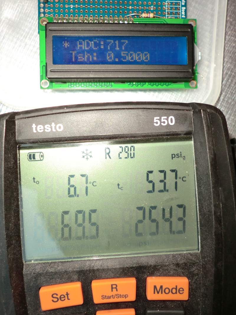 The ADC Value is 717, which is 7.17C SST. The Testo says 6.7, and is connected closer to the compressor. The P/T chart works! Tsh is superheat of 0.5C which is measured using a pair of thermal probes strapped to the input and output of the coil. The EEV sits smack in the middle of its range, and as you can see from the frost shot above, allows dialling the evap temperature right down (the frost was at -35C). All the controls do exactly what they are supposed to, and the EEV seems perfectly sized. I'm ecstatic! Yeeeeeha |
|
|
|
|
02-16-12, 11:00 AM
|
#7 | |
|
Supreme EcoRenovator
Join Date: Mar 2009
Location: Portland, OR
Posts: 4,004
Thanks: 303
Thanked 723 Times in 534 Posts
|
Quote:
-AC_Hacker
__________________
I'm not an HVAC technician. In fact, I'm barely even a hacker... |
|
|
|
|
|
02-18-12, 09:58 AM
|
#8 |
|
Supreme EcoRenovator
Join Date: Mar 2009
Location: Portland, OR
Posts: 4,004
Thanks: 303
Thanked 723 Times in 534 Posts
|
BradC,
 Regarding gear, how do you like the Testo 550 seen in a previous photo? How useful has it been in setting up your equipment? How useful has it been in understanding what's going on with the machines you're working on? Are there extra accessories for it that are required to get full use out of it? Also, there's some kind of proto board tool in the photo that I assume is the PIC controller for the EEV... What's with the readout? And lastly, I would like to know everything about your EEV development here. It would be a significant milestone for DIY folks to be able to incorporate this kind of intelligent control into their projects. There was another guy from Australia who was just starting to work with them, but unfortunately he 'dropped off the radar' before I could find out what he was doing. He was doing a water source air conditioning system earlier in the Manifesto thread... don't know if you saw it. Impressive work. And lastly, it would be useful to understand the climate factors that you have in your area. There is a website that will calculate your monthly heating and also cooling degree days. Maybe you could do it for Celsius & Fahrenheit, so it would have relevance for a wider audience. -AC_Hacker
__________________
I'm not an HVAC technician. In fact, I'm barely even a hacker... Last edited by AC_Hacker; 02-18-12 at 10:19 AM.. |
|
|
|
|
02-18-12, 08:30 PM
|
#9 | ||||
|
Apprentice EcoRenovator
Join Date: Dec 2010
Location: Western Australia
Posts: 148
Thanks: 1
Thanked 48 Times in 34 Posts
|
Quote:
When manually calculating superheat and subcooling, I had difficulty accurately measuring the pipe temperature and accurately reading the gauges (one thing the Testo has done is prove that my cheap E-bay gauge manifold is actually quite accurate). It takes a number of sources of inaccuracy out of the measurements and frees me up to concentrate on what the system is actually doing. Quote:
I'm using Dallas DS18B20 digital one wire temperature sensors. I have them : - In the free air of the roof space measuring ambient in the roof - In the return air box measuring return air temp - In the fan coil unit measuring supply air temp - On the liquid pipe (supply) at the fan coil - On the vapor pipe (return) at the fan coil I also have a pressure sensor on the suction pipe service valve at the compressor/condenser unit. The display you see in the photo says ADC: 717 (which means the SST is 7.17 Degrees C per the in-built PT chart). Tsh: is 0.5C and is calculated with the temperatures between the input and output of the coil rather than the SST. At the moment I'm still coming to grips with how things work and what to do under certain conditions so I can write an algorithm to control things manually. So the rotary encoder on the front panel allows me to directly control the EEV motor. Some of the responses to the control seem quite counter intuitive at the moment, so I need to have a closer look at the way I have things set up to get a handle on what is going on. I think I might need some heatsink compound to better couple the thermal probes to the pipework. Quote:
An accurate profile of temperatures won't really explain our cooling needs as we have wildly varying humidity. It might be 31 and dry and we won't need the AC, or it could be 26 and really humid, so we'll run the AC to dry out the air. Quote:
I'll keep this thread updated as I make progress on the control system. Like the rest of it, there's no rocket science involved. |
||||
|
|
|
|
02-19-12, 02:17 AM
|
#10 | |
|
Supreme EcoRenovator
Join Date: Mar 2009
Location: Portland, OR
Posts: 4,004
Thanks: 303
Thanked 723 Times in 534 Posts
|
Quote:
It probably looks better when you drop it in a spreadsheet. Not knowing any better, I chose the Belmont Perth airport as the weather station, I chose for the 'breakdown' the choice marked "average". and I let it average over the last five years. Columns marked "C" and "G" have the heading '% Estimated'. This means the number of months for which data was missing, and they had to do a mathematical estimate (probably an average). If it says "0" it means that they had good data for all months... etc. Columns "B" and "F" are the Degree Day data we are after. I did it once for Celsius and once for Fahrenheit. Also once for Heating and once for Cooling. Just looking at your Here is the same for Portland, Oregon (my fair city)... -AC_Hacker
__________________
I'm not an HVAC technician. In fact, I'm barely even a hacker... |
|
|
|
|
 |
| Thread Tools | |
| Display Modes | |
|
|


 Linear Mode

