
|
 03-20-12, 07:42 AM
|
#31 | |
|
Lurking Renovator
Join Date: Feb 2012
Location: Greece
Posts: 13
Thanks: 3
Thanked 3 Times in 2 Posts
|
Quote:
An other issue regarding the Condenser HX size is the capacity of the ground loop. What if the ground loop can't handle the high COP (>5) load? Have in mind that i haven't measured yet the Ground loop Capacity, nor i know how to do so. |
|

|

|
|
03-20-12, 11:50 AM
|
#32 | |
|
Apprentice EcoRenovator
Join Date: Dec 2010
Location: Western Australia
Posts: 148
Thanks: 1
Thanked 48 Times in 34 Posts
|
Quote:
|
|
|
|
|
|
03-20-12, 12:29 PM
|
#33 | |
|
Apprentice EcoRenovator
Join Date: Feb 2010
Location: Milford, DE
Posts: 106
Thanks: 5
Thanked 9 Times in 9 Posts
|
Quote:
And if a fixed compressor can't meet the load at 100% duty cycle, then you need a larger capacity compressor. I also assume such a compressor would utilize more input power to operate for a given length of time, but it may utilize more or less power in producing a given amount of Td. However all of that is a design-time concern, just as is the configuration of the evaporator and condenser. I suppose I am curious about the compressor's input power. I think it's safe to assume the compressor is electrically actuated.. How much of a variety in electric compressor design is there? How critical is the capacity matching of a compressor to the load? What is the definition of the specific physical process that the compressor performs? Is it simply compression? Volumetric compression of a gas? https://simple.wikipedia.org/wiki/Gas_compressor How is the compression ratio determined during design/selection? https://en.wikipedia.org/wiki/Compression_ratio Is dynamic compression ratio useful/utilized? Td determines the rate of heat exchange, and a lower Td should equate to a higher COP/efficiency as less work of compression is needed. A given heat load can be met with a lower Td by increasing surface area. Isn't the simple solution to increasing heat pump efficiency to increase surface areas? I guess for cooling it's not so simple because the surface temperature of the indoor coil will affect the rate of condensation and thus humidity control.. Sorry my mind is wandering! Last edited by mrd; 03-20-12 at 12:31 PM.. |
|
|
|
|
|
03-20-12, 07:59 PM
|
#34 | |
|
Apprentice EcoRenovator
Join Date: Dec 2010
Location: Western Australia
Posts: 148
Thanks: 1
Thanked 48 Times in 34 Posts
|
Quote:
The closer your evaporating and condensing temperatures, the easier it is for the compressor to pump up the gas at the evaporating pressure to reach the condensing pressure. Logically, if your evaporating temperature remains reasonably static, as your condensing temperature rises so does your power input required by the compressor. The quantity of heat moved by a refrigeration system is directly related to the refrigerant mass flow. The more refrigerant you can evaporate, the more heat you can move. To simplify it further, picture it like pumping water up a hill. The pump always moves the same quantity of water, but the higher up the hill it has to pump, the more power is required to get it there. Grab a bike pump. Pump your tyre up to 25 PSI and see how hard it is to push the pump one stroke. Now pump it up to 60 PSI and see how hard it is to pump one stroke. You are compressing the same mass of gas, however you have to work a lot harder at higher pressures. Where I used Td in my previous post, I was referring to the temperature differential between the ground loop and the condensing temperature. You correctly pointed out that the larger the exchanger surface area, the lower the Td. Now, there are two other factors here, one alters the compressor efficiency by up to 5% and the other up to 30%. Synchronous motors never rotate at their theoretical frequency. They 'slip' behind the rotating field, and the harder they work the more they slip, so your compressor actually slows down marginally as you load it up. The second is to do with the construction of the compressor. Put simply, the higher the compression ratio of the gasses, the lower the mass flow the compressor can move. On a recip this can be up to a 30% lower capacity at high pressures. This has to do with the efficiency of the valves, the dead space above the piston, ring blowby and other mechanical inefficiencies. The best for this at the moment are scrolls, and the worst are recips. Scrolls lose up to 10%, recips up to 30%. So, higher the pressure differential, the lower the mass flow for the same power input and the higher the power input. There is your COP hit. Vlad made a comment about removing the metering device making Te == Tc and therefore efficiency approaches infinity. If there is no difference between the two pressures, and you can get one to evaporate and one to condense then you've won. Otherwise, you are simply pumping a fluid in a loop. Either way, you still have frictional losses in the compressor, pumping losses due to fluid/gas friction in the pipework. You get better efficiency by opening a window  |
|
|
|
|
| The Following User Says Thank You to BradC For This Useful Post: | mrd (03-20-12) |
|
03-22-12, 03:03 PM
|
#35 | |
|
Supreme EcoRenovator

Join Date: Mar 2009
Location: Portland, OR
Posts: 4,004
Thanks: 303
Thanked 723 Times in 534 Posts
|
Quote:
My understanding of and experience with synchronous motors is that if they are loaded they do 'slip' but the slippage is very small (a very few degrees relative to the rotating field) and never amounts to anything like losing a whole "pole phase" (I just made that term up). As long as the load is maintained within the motor pull-out torque limitation, the synchronous motor average speed is kept constant. This occurs due to the fact that the rotor poles remain locked in relation to the rotating magnetic field that is generated by the stator winding. Also, it is possible to load a synchronous motor to the point where it will slip as much as a full "pole phase" or even more more than a full "pole phase", but that degree of slippage results in a momentary total collapse of torque, and would be easily sensed by a person who would hear it, and would see the motor shaking and shuddering much more than a small amount. -AC
__________________
I'm not an HVAC technician. In fact, I'm barely even a hacker... Last edited by AC_Hacker; 03-22-12 at 03:08 PM.. |
|
|
|
|
|
03-22-12, 07:40 PM
|
#36 | |
|
Apprentice EcoRenovator
Join Date: Dec 2010
Location: Western Australia
Posts: 148
Thanks: 1
Thanked 48 Times in 34 Posts
|
Quote:
Induction motors use slip to generate torque, so the greater the slip, the greater the torque. This means the more you load the motor the slower it rotates (the slip is relatively quite small, but it's there). |
|
|
|
|
|
12-09-12, 02:06 AM
|
#37 |
|
Apprentice EcoRenovator
Join Date: Dec 2010
Location: Western Australia
Posts: 148
Thanks: 1
Thanked 48 Times in 34 Posts
|
It works!
Photos to come. I've just gassed it up and got it running. Code:
Values: Te:16.5 Teh:18.8 Tsh:2.3 Valve:0237 SST:6.3 Tr:27.1 Ts:13.1 Td:14.0 Roof:49.0 Values: Te:16.5 Teh:18.6 Tsh:2.1 Valve:0237 SST:6.7 Tr:27.0 Ts:13.0 Td:14.0 Roof:49.0 Values: Te:16.5 Teh:18.5 Tsh:2.0 Valve:0237 SST:6.3 Tr:27.0 Ts:13.0 Td:14.0 Roof:49.0 Values: Te:16.5 Teh:18.5 Tsh:2.0 Valve:0238 SST:6.2 Tr:27.0 Ts:13.0 Td:14.0 Roof:49.0 Values: Te:16.4 Teh:18.5 Tsh:2.1 Valve:0238 SST:6.0 Tr:27.0 Ts:13.0 Td:14.0 Roof:49.1 With the water cooled condenser I'm condensing at about 25.5C (Can get it down below 25 if I just dump the return water so I need a bigger injection bore. Have about 8PSI back pressure right now). After about 30 mins of running the return air is at 27C. I'm getting 14K drop across the evaporator and the SST is steadily dropping (as is the temp inside the house). Supply air is down below 13C (Could never get better than about 17 before). Summary. The as-delivered air cooled configuration was undersized for the house. The condenser was too small for the system (it was a badly designed system to start with which is why I got it for almost nothing). By replacing the condenser with a large (~8M2 area!) BPHX in an open loop bore water configuration I've increased the system capacity enough that it is now well sized for the house. The total power consumption has dropped, but until I get a chance to set it up and do some proper measurements I won't know properly by how much. The original system load was about 14-15 A. It's now at 13.7 with a fully loaded hot house. Original condenser fan was about 0.1A Water pump is 1.2A The water pump drops to about 0.8A with no back pressure, and the condensing temperature drops further reducing the compressor load. So, low side pressure is around ~66PSI and high side ~130. As the SST drops the system mass flow drops and the compressor current trends downward. Have only had it running for about an hour, so it's all very preliminary but after such a big buildup it's nice to have your assumptions vaguely validated. When the flow meter arrives, I'll be able to properly quantify the actual capacity by measuring the energy being rejected into the HX water and subtracting the system power input. I guess it's time to build the next iteration with the scroll compressor and VSD I have had waiting in the wings. |
|
|
|
|
12-10-12, 05:10 AM
|
#38 |
|
Apprentice EcoRenovator
Join Date: Dec 2010
Location: Western Australia
Posts: 148
Thanks: 1
Thanked 48 Times in 34 Posts
|
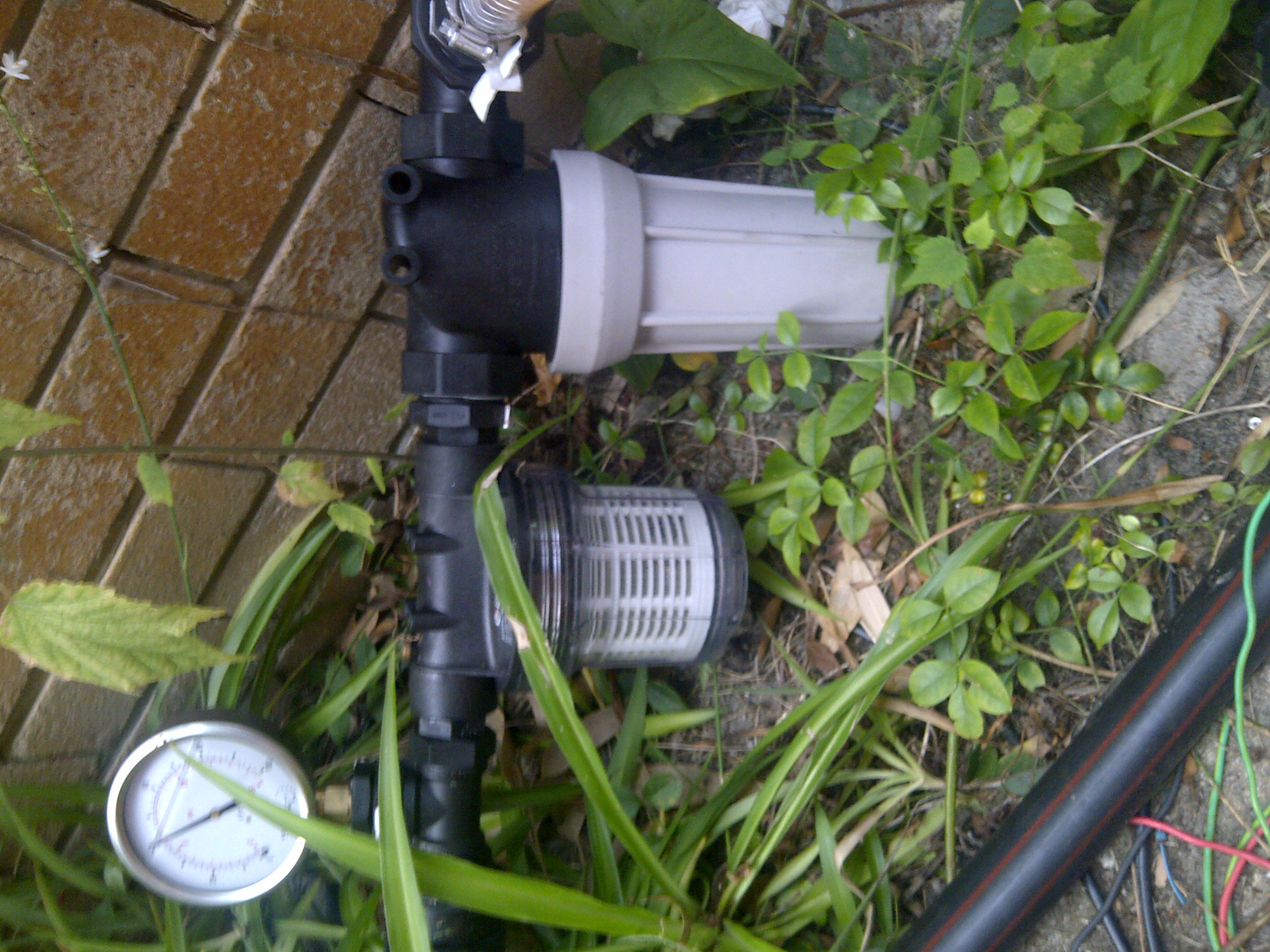 Water fine filter and pre-filter. From memory the fine filter is #100 mesh. 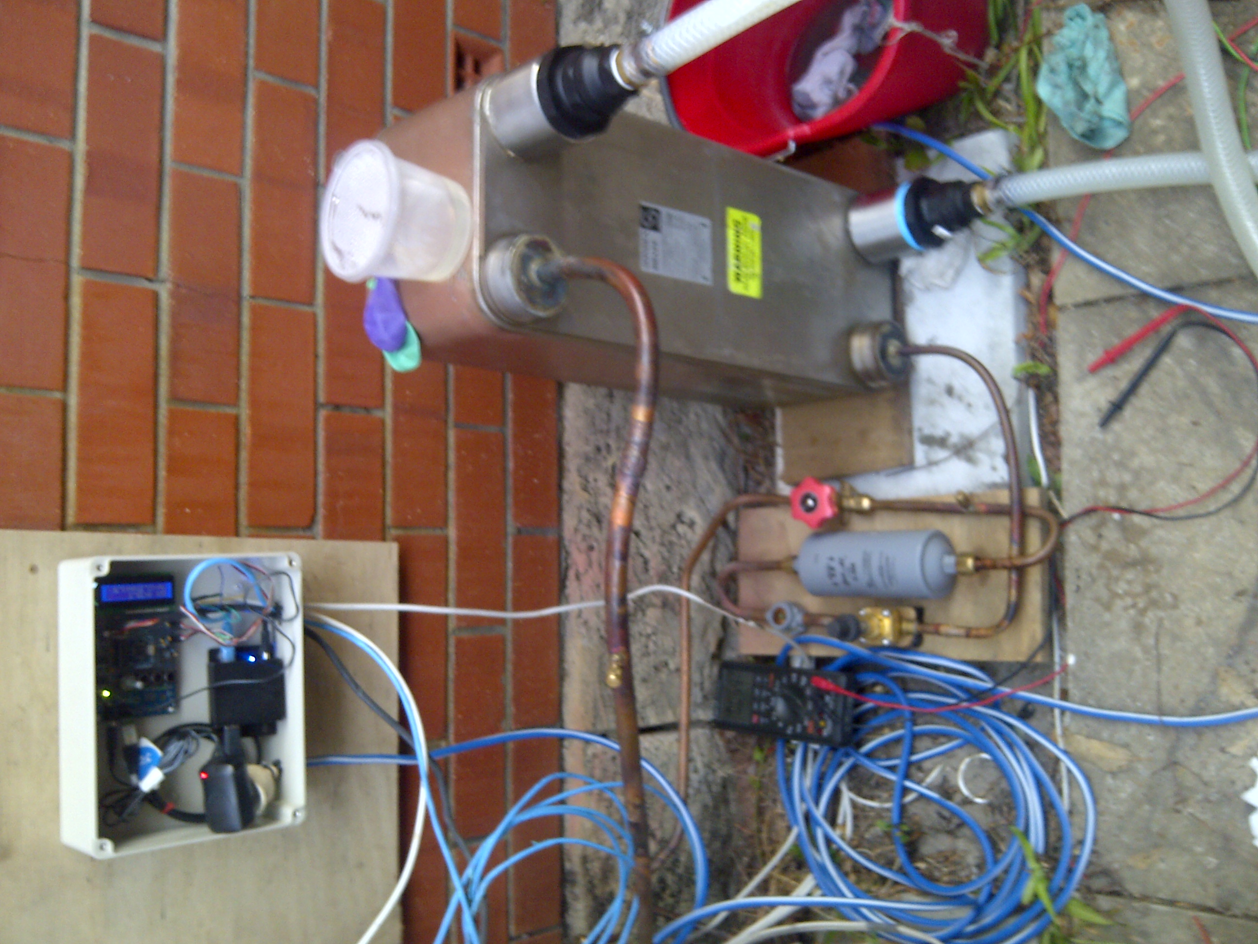 The whole assembly sitting next to the compressor/condenser unit. 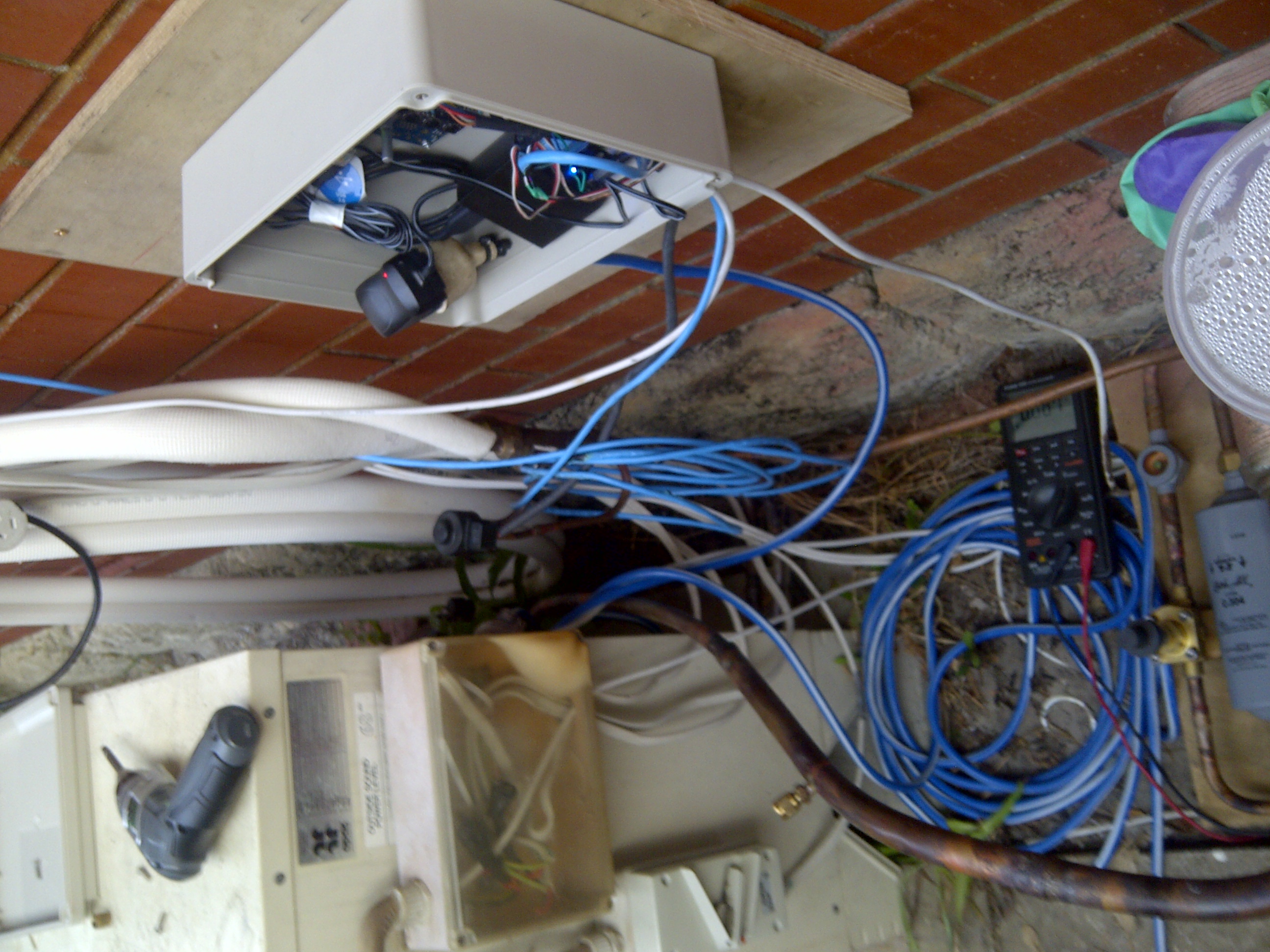 The Rats nest of cabling. The looong blue cable is a CAT-5 that I'm using with a USB extender, so I can tune,tweak & develop without having to go outside. It's all looped around the Ex-Daikin EXV. 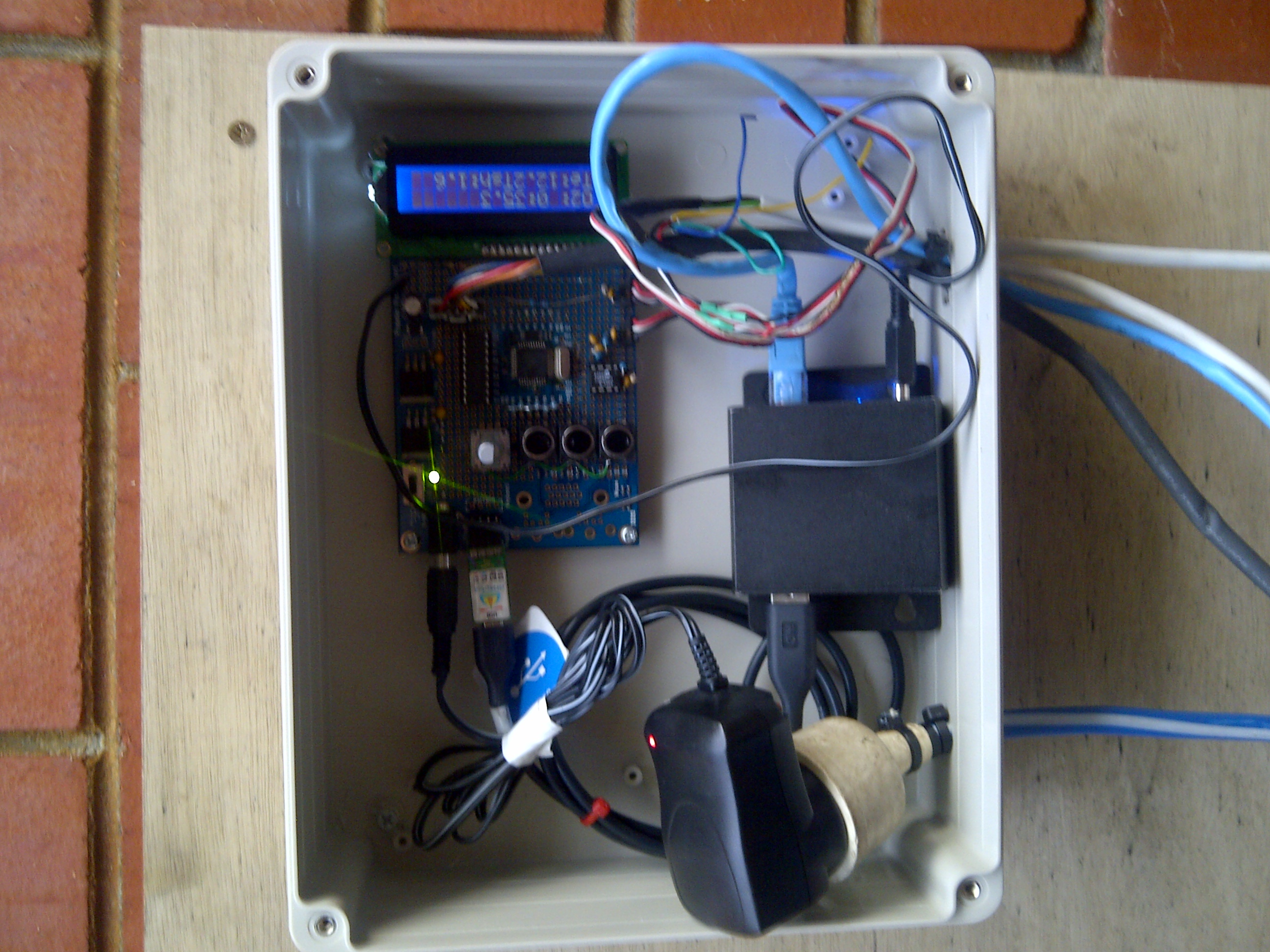 The Smarts. Control board + Dirty PSU and USB extender in a waterproof enclosure. 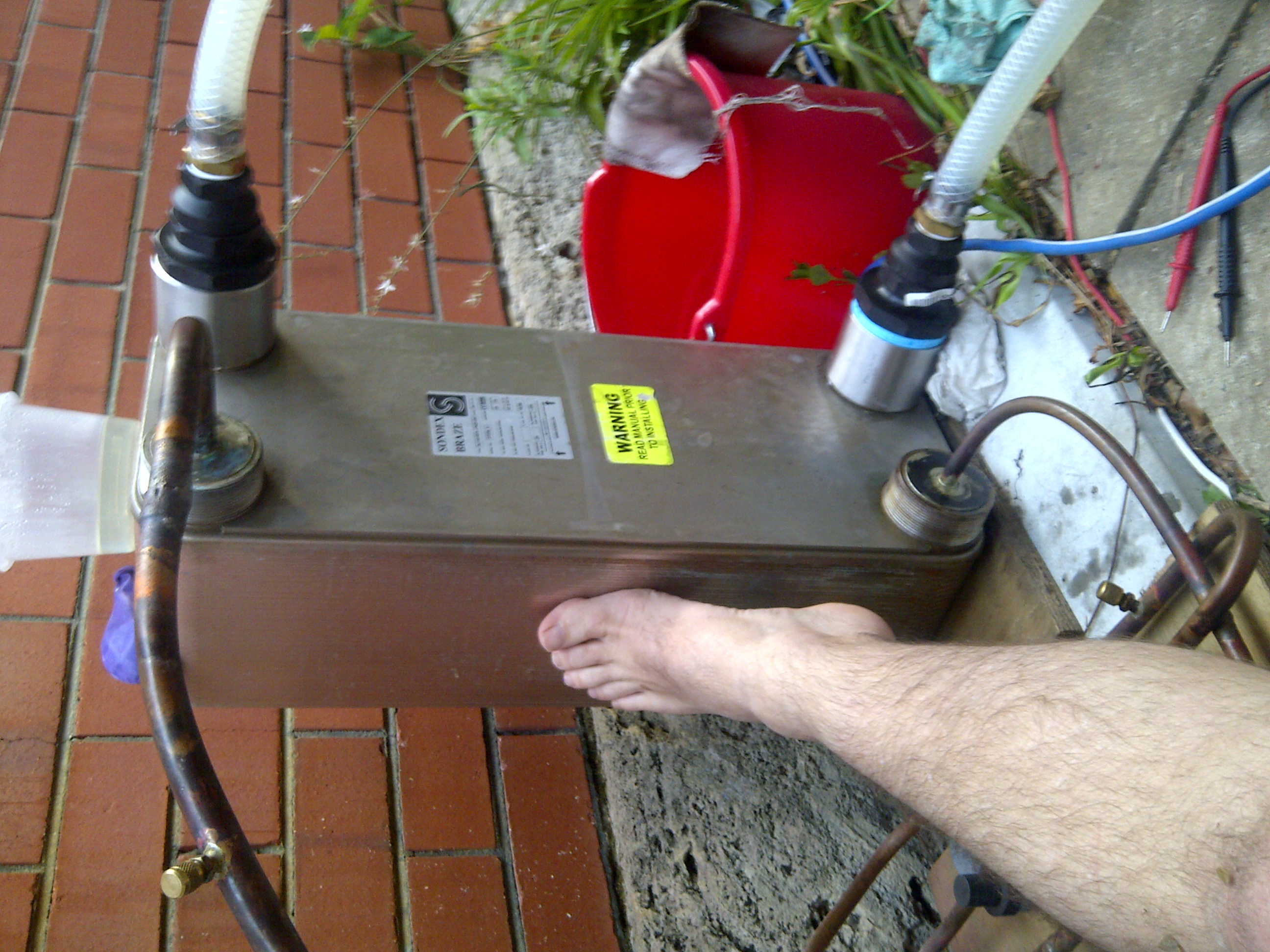 The BPHX with my foot for scale. Found a number of nasty bugs in my stepper code today which were causing erratic EXV operation. Also found a neat-o Daikin service manual that details the PI control for their split heads. It confirmed my theory that they use a pair of thermistors for superheat control and not a thermistor and pressure sensor. I need to re-seat and insulate my gas & vapor line sensors. They are obviously not making good contact with the pipe and therefore reporting a significant heat gain through the insulation. Another weekend job. As the heat load in the house has dropped, I've lost another 250W of compressor power consumption, so things are getting more efficient as I get the tuning right. I think it's way overcharged now. My subcooling is up around 4.5K. That HX holds about 8L of fluid and with the way I've configured the liquid port I'm never going to get it properly drained. I suspect I had the evaporator really, really flooded when I charged it up (due to the aforementioned stepper bugs), so I might pump it down when I get a chance and re-charge it. It has about 2KG of gas in it now (which works out at about 4L). I calculated the Evap to hold 1.5L and another 300ml in the lines (total circuit 1.79). I wonder how much liquid that monster filter/drier holds ? I've noticed that air in the water loop causes a massive rise in back pressure in the injection well. It can make the pressure gauge run off the scale (>15PSI). I've manually bled it and got the back pressure back down to about 6 PSI. I'll have to get an automated air bleed valve. Progress is being made! |
|
|
|
|
12-20-12, 12:36 AM
|
#39 |
|
Supreme EcoRenovator
Join Date: Mar 2009
Location: Portland, OR
Posts: 4,004
Thanks: 303
Thanked 723 Times in 534 Posts
|
Brad_C.,
I think this post slipped by me some how. Quite an amazing assembly you have crafted there. So, have you had time to work with the unit and get the tuning more to your liking? As I recall, your over-sized HX was an act against conventional wisdom, but you powered through anyway. Have you had enough experience with the system yet to know if the efficiency of the overall configuration is as good as you expected it to be? I don't recall if you supplied much detail previously, regarding the Ground Source (or Ground Sink in this case) part of the system. I think that I may have under-estimated the importance of that part of my system. Best, -AC
__________________
I'm not an HVAC technician. In fact, I'm barely even a hacker... |
|
|
|
|
12-20-12, 08:03 AM
|
#40 | ||
|
Apprentice EcoRenovator
Join Date: Dec 2010
Location: Western Australia
Posts: 148
Thanks: 1
Thanked 48 Times in 34 Posts
|
Quote:
Quote:
Having said that, my EEV control algorithm is terrible. It works, but it hunts a bit and is very application specific with all sorts of magic tuning variables. Needs work. I almost wished I'd done the HX first and the EEV later. At least that way I'd be able to quantify the difference somewhat. As it is, with the EEV already in and running, changing the condensing temp from ~55C to ~25C made almost no difference except to increase the capacity of the system, reduce the compressor current draw and make the EEV open wider. I don't want to make any statement about efficiency, as until my flow meter arrives I can't quantify anything positively. All I can say is at the moment I get much colder return air for a smaller net current draw. (was 17C, now 13C and net power saving of 750W). I'm as happy as a pig in poo to be frank. Now, I've spent more on the HX than I can recoup in a reasonable amount of summer days power saving. Having said that, I got the heat pump for almost nix, so in the scheme of things I'm still ahead of the game had I bought a normal R410A air sourced unit and I'm generating more cold for less watts. That's what we're here for isn't it? As for the ground part of things, I'm *really* lucky here. My water table is about 10 feet down. The water is very clean, low in iron & bacteria and fairly neutral Ph. So I pump it out of the ground, run it through the strainers, HX and poke it back in the ground about 20M (66ft) from where I pull it out. My ground water is stable at about 20C and I *think* I'm flowing about 35 L/pm (Can't convert that into Gallons as I'm not sure which Gallon to use). My injection well back pressure is down to about 5PSI on average. A bigger well is planned to reduce the back pressure which will reduce the condensation temp by increasing the water flow, and will also reduce the pump current. When the flow meter arrives, I'll put it between the first and second filter screens and measure the in/out water temps. That will give me exact heat being rejected into the ground and I can calculate the system COP from there. Progress is being made. Interestingly (for me anyway), I've read recently about some super high efficiency systems that condense almost as cool as they evaporate. They've put a liquid refrigerant pump before the metering device to ensure enough mass flow to run the system. Wish I had a link handy. Different anyway. The crux seems to be, the higher you evaporate and lower you condense the higher your COP. You may need a different metering device (or a liquid pump) to ensure the correct refrigerant flow, but the theory holds sound. |
||
|
|
|
| The Following User Says Thank You to BradC For This Useful Post: | Roostre (01-31-18) |
 |
|
|


 Linear Mode

