
|
 02-28-12, 07:07 PM
|
#21 | |||
|
Apprentice EcoRenovator
Join Date: Dec 2010
Location: Western Australia
Posts: 148
Thanks: 1
Thanked 48 Times in 34 Posts
|
Quote:
I'm hoping that my generic Scroll compressor copes with the VSD. Some motors can suffer severe stator eddy current losses with VSD drives, and overheat. I don't really want to have to spring for a new compressor if I can avoid it (another $1k or so). The VSD runs the compressor fine, but of course I've not been able to do any extended run tests yet. Quote:
- De-superheating - 80% Vapor - 50% Vapor - 20% Vapor - Pure liquid / Subcooling It's quite a complex set of calculations. I did it once (about a year and a half ago). This time I just got on the phone to the HX vendor, gave him my numbers and he plugged them into his simulator software and came up with the same condensation temperature I did originally. All the HX design software I've seen has been very manufacturer specific, and the don't unlock features like refrigerant side calculations unless you pay a load, or sell lots of their product. Therefore I've not seen anything out there we as DIY'ers can get our hands on. Also, a lot of the software lacks R290. I ask for sizes based on R22 and it works out pretty close. The other thing about condenser sizing, is everyone seems to do it differently. I've seen algorithms that have 30 or 40 iterations and sub-steps. I actually don't recall now where I got the heat transfer coefficients for different vapor quality levels. I'll have a dig through my reference material and see if I can dredge it up. I've got 8.5M2 of surface area in the condenser. The vendor told me I could halve that, but at the expense of having to double water flow. Now given doubling water flow causes the power to rise with the square, it meant a pump 4 times as powerful, so my overall COP would have dropped. I would have saved $600 on the HX, but needed a bigger pump and more power consumption. HX design for evaporators and water to water is _much_ easier. Quote:
I have a strong background in electronics, embedded control and therefore control algorithms. My philosophy is that a control system can quickly be developed to solve any problem economically. Planning the control system before having a defined problem to solve is a bit like arguing over the colour you want to paint a bikeshed before having worked through the problem of designing and building it. I'm happy to share the designs and algorithms I'm developing and working with, particularly with regard to the EEV's, but I tend to be very "hands on" when it comes to developing stuff like that. Unless the hardware is built and I can get measurements from it, I tend to shy away from theorising about it. BTW, SSR's are great for compressors. I built a custom thermostat control for an old 1/2hp window banger years ago that used an off the shelf SSR to control the compressor. It seemed to cope with the inrush start current fine, and probably cycled the compressor every 20 minutes for about 3 years before I decommissioned it. I used this : SSR5A - SPST 3-15VDC 5A Solid State Relay - Technical Data You guys in the US are unlucky with 120V. At 240V we can use a much smaller unit, and therefore sustain much smaller losses across the device. |
|||

|

|
|
02-28-12, 08:12 PM
|
#22 | |
|
Apprentice EcoRenovator
Join Date: Dec 2010
Location: Western Australia
Posts: 148
Thanks: 1
Thanked 48 Times in 34 Posts
|
Quote:
It's based on an average U value of ~150 which appears to be closeish as an average condenser value. Taking a gross average is not in any way accurate, but it saves the whole iterative process of multiple areas/zones. To make it easy, It does not account for any subcooling. It also works for an evaporator if you change the U to 800 and ignore the fact all the numbers go negative. If you use a U of about 1500, it will work for water to water. The real juice is in calculating the LMTD for the HX. It's amazing how fiddling the input/output numbers slightly can massively change the theoretical heat transfer coefficients. http://www.fnarfbargle.com/private/1...y_HX_Calcs.ods Now, this spreadsheet works for me. Remember, I'm relatively un-educated and generally work by rule of thumb. It may be riddled with mistakes, or contain gross logical errors, but when I put in the numbers, I get the result I think I should. |
|
|
|
|
|
03-05-12, 02:20 AM
|
#23 |
|
Apprentice EcoRenovator
Join Date: Dec 2010
Location: Western Australia
Posts: 148
Thanks: 1
Thanked 48 Times in 34 Posts
|
So I had some time this weekend to sit and try out some EEV superheat control algorithms.
I tried several variants of PID algorithms, and while I could get them to work they were impossibly fussy to tune, prone to damped oscillation and overshoot and in general quite a bear to work with. I then did some research into fuzzy logic, and came up with a bastardized version with an incredibly simple algorithm that tracks and seems to work. This is not a true fuzzy logic algorithm, it's much rougher and less accurate, but is very simply implemented as a series of IF statements. The algorithm is called every 30 seconds, and its return value is used to turn the EEV as required. We take the current superheat and set point, and derive the current error (setpoint-superheat) and the current rate and direction of change (has the superheat risen or fallen since the last run?). If the error is positive and superheat is falling : close the valve a bit If the error is negative and superheat is rising : open the valve a bit If the error is negative and superheat is stable : close the valve a little bit If the error is positive and superheat is stable : open the valve a little bit The idea is to leave the valve alone as much as possible, so if we are away from the setpoint, but moving towards it we don't move the valve unless things settle and we need to give it a nudge. "a little bit" is one valve step. "a bit" is the current error in C * 10 (so 1.1C is 11) + the current direction (which is measured in 10ths of a C also). So depending on how far the setpoint is and how fast it is changing, it moves the valve somewhere between 1 and 10 steps. Depending on the heatload in the house, and the ambient and wind outside, the valve seems to vary from between about 350 to 400 steps (measured from completely closed). This means the valve is probably slightly undersized for this application (no real surprise as it came of an R410 unit and I'm using R290), but the range of adjustment is certainly enough to make it work. Here's a sample controller output in 30 second datapoints Te is thermistor on evaporator liquid pipe Teh is thermistor on evaporator suction pipe Tsh is calculated superheat from the previous two values Valve is valve absolute position in steps SST is Saturated Suction temp measured at suction service valve Tr is return air temp measured at return air box Ts is supply air temp measured with thermistor inside fan coil Td is calculated difference between supply and return air temps Roof is free air temperature inside my roof space (it's hot outside and I have dark tiles) c_err is current calculated error between superheat and set point in 10ths of a C o_err is c_err from previous loop c_dir is current superheat direction (stable, falling, rising) in 10ths of a C o_td is a long term (16 samples) average of Td in 10th's of a C d_td is a current difference between o_td and Td in 10th's of a C Current Superheat set point is 0.9C Code:
Values: Te:20.7 Teh:21.6 Tsh:0.9 Valve:0391 SST:9.5 Tr:29.2 Ts:17.7 Td:11.5 Roof:51.4 c_err: -1 c_dir: -1 mag: 0 o_td: 114 d_td: 0 Values: Te:20.6 Teh:21.6 Tsh:1.0 Valve:0391 SST:9.5 Tr:29.1 Ts:17.6 Td:11.5 Roof:51.4 c_err: 0 c_dir: 1 mag: 1 o_td: 114 d_td: 3 Values: Te:20.6 Teh:21.5 Tsh:0.9 Valve:0391 SST:8.9 Tr:29.3 Ts:17.6 Td:11.7 Roof:51.3 c_err: -1 c_dir: -1 mag: 0 o_td: 115 d_td: 1 Values: Te:20.5 Teh:21.5 Tsh:1.0 Valve:0391 SST:9.5 Tr:29.2 Ts:17.6 Td:11.6 Roof:51.3 c_err: -2 c_dir: -1 mag: 1 o_td: 115 d_td: 2 Values: Te:20.5 Teh:21.6 Tsh:1.1 Valve:0392 SST:9.5 Tr:29.3 Ts:17.6 Td:11.7 Roof:51.3 c_err: -1 c_dir: 1 mag: 2 o_td: 115 d_td: 0 Values: Te:20.5 Teh:21.5 Tsh:1.0 Valve:0392 SST:9.5 Tr:29.1 Ts:17.6 Td:11.5 Roof:51.3 c_err: -2 c_dir: -1 mag: 1 o_td: 115 d_td: 2 Values: Te:20.5 Teh:21.6 Tsh:1.1 Valve:0393 SST:9.5 Tr:29.4 Ts:17.7 Td:11.7 Roof:51.3 c_err: -2 c_dir: 0 mag: 2 o_td: 115 d_td: 1 Values: Te:20.5 Teh:21.6 Tsh:1.1 Valve:0394 SST:9.5 Tr:29.3 Ts:17.7 Td:11.6 Roof:51.3 c_err: -1 c_dir: 1 mag: 2 o_td: 115 d_td: 1 Values: Te:20.5 Teh:21.5 Tsh:1.0 Valve:0394 SST:9.5 Tr:29.3 Ts:17.7 Td:11.6 Roof:51.3 c_err: 0 c_dir: 1 mag: 1 o_td: 115 d_td: -2 Values: Te:20.6 Teh:21.5 Tsh:0.9 Valve:0394 SST:9.5 Tr:29.0 Ts:17.7 Td:11.3 Roof:51.3 c_err: 0 c_dir: 0 mag: 0 o_td: 115 d_td: -3 Values: Te:20.6 Teh:21.5 Tsh:0.9 Valve:0394 SST:10.1 Tr:29.0 Ts:17.8 Td:11.2 Roof:51.3 c_err: 0 c_dir: 0 mag: 0 o_td: 115 d_td: -2 Values: Te:20.6 Teh:21.5 Tsh:0.9 Valve:0394 SST:10.1 Tr:29.1 Ts:17.8 Td:11.3 Roof:51.2 c_err: 0 c_dir: 0 mag: 0 o_td: 115 d_td: -1 Values: Te:20.7 Teh:21.6 Tsh:0.9 Valve:0394 SST:10.1 Tr:29.2 Ts:17.8 Td:11.4 Roof:51.2 c_err: 1 c_dir: 1 mag: 0 o_td: 114 d_td: -2 Values: Te:20.8 Teh:21.6 Tsh:0.8 Valve:0394 SST:10.1 Tr:29.0 Ts:17.8 Td:11.2 Roof:51.2 c_err: 1 c_dir: 0 mag: 1 o_td: 114 d_td: 0 Values: Te:20.8 Teh:21.6 Tsh:0.8 Valve:0393 SST:9.5 Tr:29.2 Ts:17.8 Td:11.4 Roof:51.1 c_err: 0 c_dir: -1 mag: 1 o_td: 114 d_td: 0 Values: Te:20.7 Teh:21.6 Tsh:0.9 Valve:0393 SST:9.5 Tr:29.2 Ts:17.8 Td:11.4 Roof:51.1 c_err: 1 c_dir: 1 mag: 0 o_td: 114 d_td: -2 Values: Te:20.8 Teh:21.6 Tsh:0.8 Valve:0393 SST:10.1 Tr:29.1 Ts:17.8 Td:11.3 Roof:51.1 c_err: 2 c_dir: 1 mag: 1 o_td: 114 d_td: 1 Values: Te:20.8 Teh:21.5 Tsh:0.7 Valve:0392 SST:9.5 Tr:29.3 Ts:17.8 Td:11.5 Roof:51.1 c_err: 1 c_dir: -1 mag: 2 o_td: 114 d_td: -2 Values: Te:20.7 Teh:21.5 Tsh:0.8 Valve:0392 SST:9.5 Tr:29.0 Ts:17.8 Td:11.2 Roof:51.1 c_err: 0 c_dir: -1 mag: 1 o_td: 114 d_td: 1 Values: Te:20.6 Teh:21.5 Tsh:0.9 Valve:0392 SST:9.5 Tr:29.2 Ts:17.7 Td:11.5 Roof:51.0 |
|
|
|
|
03-05-12, 08:43 PM
|
#24 | |
|
Apprentice EcoRenovator
Join Date: Feb 2010
Location: Milford, DE
Posts: 106
Thanks: 5
Thanked 9 Times in 9 Posts
|
Quote:
I read up on PID algos on wikipedia, very interesting. It indicates loop tuning can be difficult. Your fuzzy logic solution feels more intuitive, however. There must be some response time between when the EEV is adjusted and Tsh changes. Perhaps there are few enough variables in the system affecting that response time to incorporate the anticipated reaction in code..? |
|
|
|
|
|
03-05-12, 10:31 PM
|
#25 | ||
|
Apprentice EcoRenovator
Join Date: Dec 2010
Location: Western Australia
Posts: 148
Thanks: 1
Thanked 48 Times in 34 Posts
|
Quote:
Indoor temperature is maintained with bang bang control, so setpoint reached just cycles the compressor off. It's quite undersized, so it never cycles off during the day anyway. Quote:
A lower superheat floods the coil and tends to result in a higher SST (more pressure in the suction line). A higher SST results in a higher overall coil temperature and less heat transfer (as the refrigerant is boiling at a higher temperature). Conversely, a higher superheat means less refrigerant in the coil and as a result the SST drops, so the refrigerant that is in there is a lower temperature, but as less of the coil is used it sucks less heat out of the air. It's a bit of a delicate balance. The thermal intertia in the system currently results in a control-response delay of about 20 seconds, so I run the loop every 30 seconds and it maintains a good hold over the superheat. There are not many step response type load changes in a system like this, so once it locks on it follows pretty well. Hopefully the heat exchangers and water pump will arrive this week and I can get to work on my open-loop GSHP solution. That will be a lot more fun to play with (and certainly more applicable to this forum). I have the source and return wells sunk and tested, I just have to plumb them up now. |
||
|
|
|
|
03-07-12, 10:41 PM
|
#26 |
|
Apprentice EcoRenovator
Join Date: Dec 2010
Location: Western Australia
Posts: 148
Thanks: 1
Thanked 48 Times in 34 Posts
|
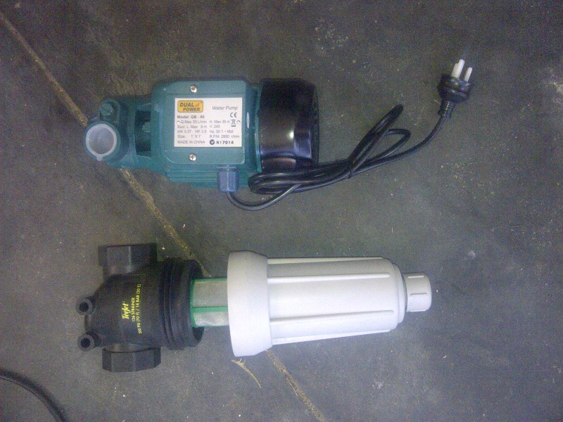
32L/minute (~7GPM) water pump and #100 stainless steel mesh screen. BPHX manufacturer recommends #50 screen, so I figured smaller is better.
 New HX's arrived this morning 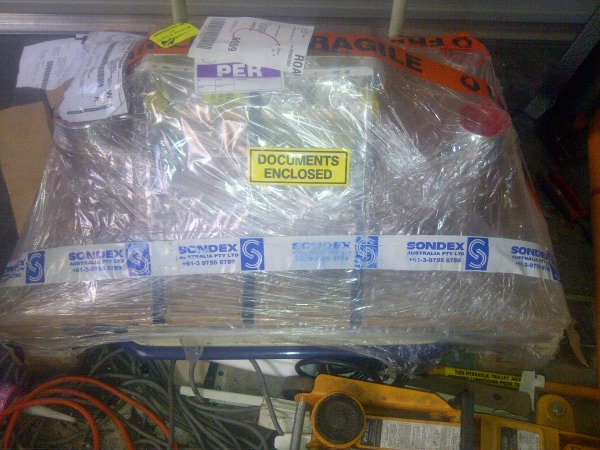 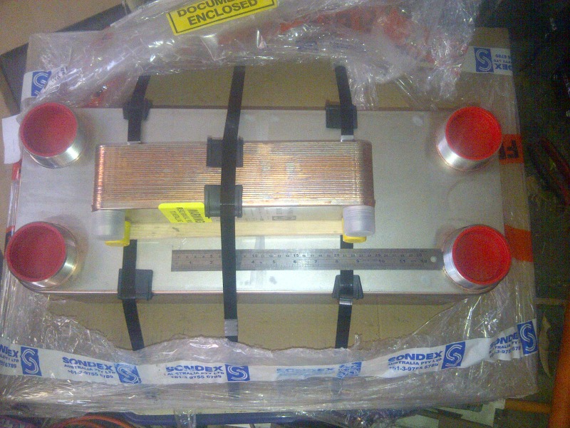 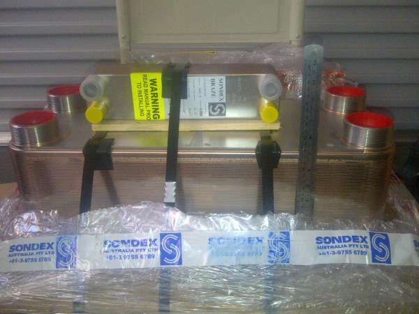 The "little one" (which is a foot long) on top is a SLHX. I now need to find some copper rod > 63mm in diameter to turn up some adapters to be able to braze the copper lines in there. 63mm seems to be pretty close(ish) to about 2 1/2", but not close enough that any off the shelf adapters fit. The big exchanger has a fluid volume of 18L. Won't be needing any liquid receiver on this system! <edit> Oh it must be Christmas. Just got notification my sample EEV's are on their way from China. Last edited by BradC; 03-08-12 at 01:30 AM.. Reason: More christmas |
|
|
|
|
03-10-12, 03:06 AM
|
#27 |
|
Apprentice EcoRenovator
Join Date: Dec 2010
Location: Western Australia
Posts: 148
Thanks: 1
Thanked 48 Times in 34 Posts
|
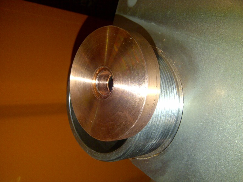
Copper adapter plate hot of the lathe
 With 3/4" Pipe 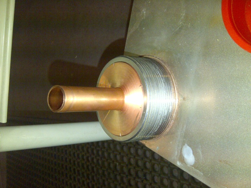 Ready for Brazing 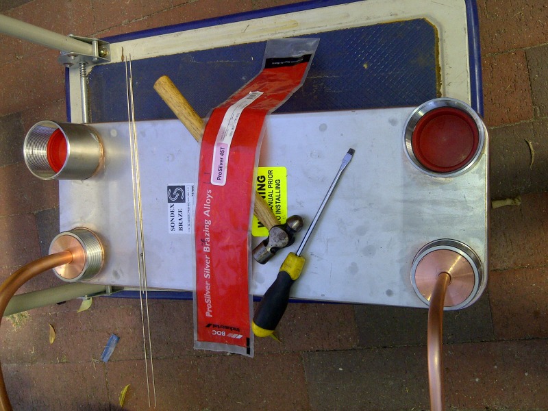 All brazed up and on the Vac pump 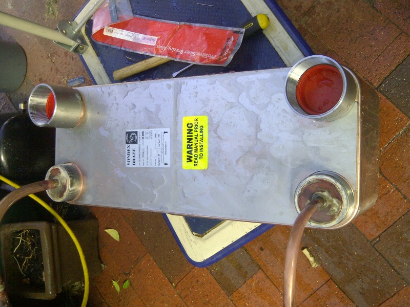 Broke my vac pump again. Seems like another liquid slug took out the second stage valve. Will continue to evacuate on the first stage until all the water is gone before i re-build it again. Turns out they use water to hydro test both sides of the exchanger before it goes out, and there was a fair bit of water in there. <edit> Vac pump had some dirt lodged under the reed. A clean and oil change and it's good to go. Last edited by BradC; 03-10-12 at 03:37 AM.. Reason: More info |
|
|
|
|
03-15-12, 10:58 PM
|
#28 |
|
Apprentice EcoRenovator
Join Date: Dec 2010
Location: Western Australia
Posts: 148
Thanks: 1
Thanked 48 Times in 34 Posts
|
Pretty valves all in a row
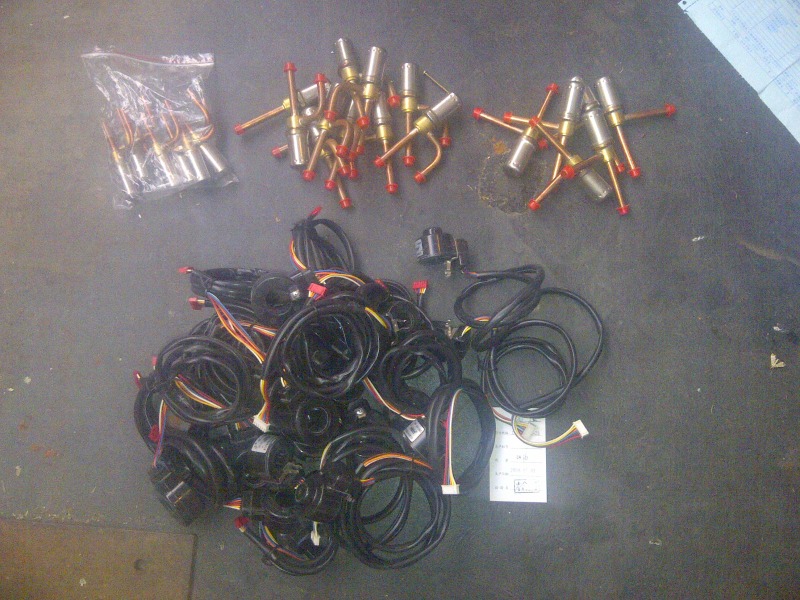 They are supposed to be fitted with a #100 mesh pre-filter, but I can't find any available to the general public. I figure a catch-all filter-drier should do the job. I got some 1.6, 2.2 & 3 mm orifice valves (~2 / 3 / 6 Ton R22 capacity). I figure the 2.2 will do for what I need, but I have some spares to experiment with. The larger valve bore is to compensate for the much reduced high side pressure. On a more disappointing note, in the process of reconfiguring my bore casing to allow a more permanent source of water without disrupting the reticulation, I appear to have cracked my casing or spear. In any case, I've completely lost any motivation I had to fix it as it was driving me mental, so I've called a bore specialist to come and un-break it for me. He's due sometime mid next week. One step forward, two steps back. |
|
|
|
|
03-15-12, 11:36 PM
|
#29 | |
|
Supreme EcoRenovator

Join Date: Mar 2009
Location: Portland, OR
Posts: 4,004
Thanks: 303
Thanked 723 Times in 534 Posts
|
BradC,
Quote:
Help me understand what's going on here... I'm guessing that these are NOT the stepper motor controlled valves that you spoke of in an earlier post... they appear to me to NOT be proportional valves, but rather solenoid actuated valves, with 'off' and 'on' states. I'm guessing that "A" valves are the 2 Ton, "B" valves are the 3 Ton and "C" valves are the 6 Ton valves and that pile "D" are the solenoid coils to actuate the valves. Did I get any of this right? And how are you intending to use them? -AC_Hacker
__________________
I'm not an HVAC technician. In fact, I'm barely even a hacker... |
|
|
|
|
|
03-15-12, 11:55 PM
|
#30 | |
|
Apprentice EcoRenovator
Join Date: Dec 2010
Location: Western Australia
Posts: 148
Thanks: 1
Thanked 48 Times in 34 Posts
|
Quote:
The stepper coils are 4 phase single pole stepper motors. The inside of the coil hole has the exposed poles of the stepper coils but I don't really have a camera that is any good at getting a photo of them. As for use, I plan to use a couple of them for my own system. I'm thinking about trying to adapt one of the 1.6's to fit it into my Car. I have some compressor/condenser units here that they would work well on for things like a refrigerated compressed air dryer, super bottle chiller (glycol bath) and a propane purification rig. I've also got some ideas about a VRV marine A/C system (kit form for boats). Other than that, as I managed to pick them up so cheaply I thought we could use some as a community to further the heat pump hacking goals. Ultimately I'd still like to be able to buy them in qty and sell them as part of a kit (with a suitably easy to build controller). The limitation on these valves is they are OEM parts, and you can generally only get them in Qty:1000. I figure I can do a deal with the manufacturer and get them in smaller quantities, but I'm never going to be able to get them at less than 100 at a time. Even at the 1000 price of $20 each, 100 valves is still a significant investment. |
|
|
|
|
 |
|
|


 Linear Mode

