
|
 07-19-10, 04:31 AM
|
#11 |
|
Helper EcoRenovator
Join Date: Apr 2010
Location: Wellington, New Zealand
Posts: 61
Thanks: 0
Thanked 6 Times in 5 Posts
|
As we say here in NZ, Yeah right, he's a bloody idiot, anyone who has worked on switching power supplies should have a healthy respect for high voltage electro's, engineer indeed.
I may have a simple cct for what you require, will dig it out, if I can locate the magazine article. Mike |

|

|
|
07-19-10, 05:03 AM
|
#12 |
|
Helper EcoRenovator
Join Date: Apr 2010
Location: Wellington, New Zealand
Posts: 61
Thanks: 0
Thanked 6 Times in 5 Posts
|
I found it, too old not using Fets, see Silicon Chip mag Nov 1991
This microchip note has some good info on MPPT AN1211 - Maximum Power Solar Converter - Application Notes - Details Also see Google Image Result for http://www.intusoft.com/nlpics/78/MPPT.gif for some info. Mike |
|
|
|
|
07-19-10, 09:54 AM
|
#13 |
|
Lex Parsimoniae

Join Date: Feb 2009
Location: Woburn, MA
Posts: 4,918
Thanks: 114
Thanked 250 Times in 230 Posts
|
Thanks Mike,
The AN1211 looks very interesting and it might be fun to write the program to control it. But, since I'm getting old and simple, I'm going to try to keep this project simple too.  I did get a hit on another 'pump' controller page. Power point Trackers Chris has a crude drawing of three MPP curves and he has an interesting take on what is 'good' enough to get the job done.. "Looking at figure 2 it may be noticed that the PV maximum power voltage is only within a couple of percent for differing isolation levels . This means that if a unit could be built, that would maintain the cells output voltage at a fixed value, "say - at the most predominate isolation and cell temperature", the PV cell would operate at close or near it's maximum efficiency for all isolation levels. " In other words, the very simple pump controller (see up top) can do a very good job, without the micro-management of a micro controller. All it has to do is be within range to get pretty good performance.. ~~~ I'm not against adding some amount of complexity, if it's easy to do (and un-do). If the idea of using a Photocell to lower the set-point voltage for cloudy days, could actually work, then maybe a thermistor (NTC) across the lower 3k3 (below the trim-pot) could bring up the set-point voltage a tad, on those very cool days.?. (When PV works best). If the thermistor idea worked, I wonder if just reading the air temp in the shade, would be as good as reading the temp right on the bottom a PV panel? |
|
|
|
|
07-19-10, 02:28 PM
|
#14 |
|
Lex Parsimoniae
Join Date: Feb 2009
Location: Woburn, MA
Posts: 4,918
Thanks: 114
Thanked 250 Times in 230 Posts
|
When I looked at this circuit, I assumed it wasn't a voltage step-down. But a voltage booster.
 Assuming the Supply is the PV panels, the switch a MOSFET and the load is just a big non-reactive 10 Ohm resistor, it seems to me there would be AC type voltage applied to the load when the FET is turned off.. So, the circuit is a step down for DC, but maybe it can make a little AC.?. FET On: 66vdc applied to load, via inductor. Magnetic field builds up, until the load is drawing about 6.6A. 66v x 6.6a = 435.6watts. FET OFF: Magnetic field quickly collapses inwards, generating a pulse of high voltage. Since the field is moving in the opposite direction, the polarity is reversed. The diode feeds the negative voltage-current pulse into the bottom of the load. And the +plus side is fed into the top of the load. Since the reverse-polarity pulse voltage is much higher than +66v, it's power is absorbed almost instantly into the 10 Ohm load. So, my argument is, repeated jolts of reverse-polarity of HV during the FET-Off time, will heat up the load more, because that voltage is not limited to 66v (into 10 ohms). So, on average, over time, the voltage seen by the load is going to be higher than 66v. (The resistor load doesn't know + from -). Higher voltage into a load, means it's going to dissipate more power.. Or, maybe at FET On, the XL of the coil is going to slow down the current enough to mathematically cancel out the large pulse of HV when the field comes down.?. Making the average voltage even out..?. Maybe it's time get out the books again..  Last edited by Xringer; 07-19-10 at 02:42 PM.. |
|
|
|
|
07-20-10, 05:39 AM
|
#15 |
|
Helper EcoRenovator
Join Date: Apr 2010
Location: Wellington, New Zealand
Posts: 61
Thanks: 0
Thanked 6 Times in 5 Posts
|
That article at Power point Trackers
is very informative. In the situation where you have your panels in series and supplying a purely resistive load, logically you want a circuit that supplies the max current through your load at all times. So a series current sense or a voltage sense across the load needs to be the feedback mechanism to the voltage switch circuit. If the load voltage is switched somewhat lower than the panel voltage (thus higher current) then this would give the control circuit some latitude for feedback variation. Perhaps the simple switch circuit you found above could be modified. I have never heard of that chip LM78S40, is it still available ? Cheers Mike |
|
|
|
|
07-20-10, 08:57 AM
|
#16 |
|
Lex Parsimoniae
Join Date: Feb 2009
Location: Woburn, MA
Posts: 4,918
Thanks: 114
Thanked 250 Times in 230 Posts
|
NATIONAL SEMICONDUCTOR | LM78S40CN/NOPB | LM78S40 Series MDIP-16 Pin Universal Switching Regulator Subsystem - Future Electronics
Yeah it still around for 76 cents.. And there are some good app-notes on the page too. The more I look at those Pump drivers from 'Down Under', the more I like them. The MiniMax http://www.voltscommissar.net/minimax/schemati.gif needs no feed back, it just delivers the max wattage available. The pulse action will kick in when the clouds roll in. The pulse rate will depend on the rise time of the panels and the size of the input capacitor. When the sun gets really dim, I think a photocell mod might be a neat way to get those last few watts delivered.. 14:27 edit: Really over-cast out right now. Less than 30w of power. 17volts coming in. But, when I open the cut-off switch, the open voltage jumps right up to 78 volts. I'll bet the PV could charge up some caps pretty fast, even in this light. This looks like the perfect app for a comparator controlled MOSFET.. 20:32 edit: The max power voltage for these panels (as marked on the labels) is 17.4 volts. Times 4 panels is 69.6v. If the 10 ohm load saw 69.6v, that's 6.96 amps that's 484 watts. Which would make me very happy. Typically, it's running low, about 62.6v.. Into 10 ohms, that's only about 392 watts of power. Being 7 volts low, (and 92w short of the dream wattage of 484) might be curable with a Pump controller.. Last edited by Xringer; 07-20-10 at 07:45 PM.. |
|
|
|
|
07-21-10, 07:48 AM
|
#17 |
|
Lex Parsimoniae
Join Date: Feb 2009
Location: Woburn, MA
Posts: 4,918
Thanks: 114
Thanked 250 Times in 230 Posts
|
Checked my mail this morning, and it seems that late last night,
I got real groggy and somehow ordered (10) LM339N quad comparators, (1) Capacitor 4700uf 100V and (10) IRFP150 / IRFP150N MOSFET 40A, 100V. I guess some items are cheaper by the 10 pack?  I think that 100v MOSFET should be suitable for this app. I plan to find a small heat sink to use with it. If they don't require too much gate drive, maybe I can use two in parallel. Just to be safe. 7/22/2010 8:30am edit: Morning Email said "You won"! My lowball $2 bid (+3.05 shipping) for (20) LM311 comparators (8 pin dips), means I now have a lifetime supply of comparators! Last edited by Xringer; 07-22-10 at 07:35 AM.. |
|
|
|
|
07-21-10, 10:20 AM
|
#18 |
|
Administrator

Join Date: Aug 2008
Location: Germantown, WI
Posts: 5,525
Thanks: 1,162
Thanked 374 Times in 305 Posts
|
Haha, sounds like a fun project. It'll be interesting to see how this works out.
__________________
Current project - To view links or images in signatures your post count must be 0 or greater. You currently have 0 posts. To view links or images in signatures your post count must be 0 or greater. You currently have 0 posts. & To view links or images in signatures your post count must be 0 or greater. You currently have 0 posts. |
|
|
|
|
07-24-10, 11:24 AM
|
#19 |
|
Lex Parsimoniae
Join Date: Feb 2009
Location: Woburn, MA
Posts: 4,918
Thanks: 114
Thanked 250 Times in 230 Posts
|
I've decided to try using the pump circuit, almost exactly.
Here's the real deal,  and here's my (unbuilt) hack of the same rig. 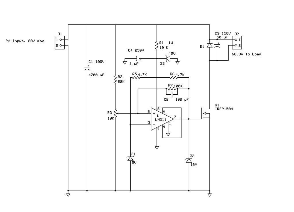 Comments? Last edited by Xringer; 10-17-10 at 06:32 PM.. Reason: Changing diagram wiring |
|
|
|
|
10-17-10, 06:48 PM
|
#20 |
|
Lex Parsimoniae
Join Date: Feb 2009
Location: Woburn, MA
Posts: 4,918
Thanks: 114
Thanked 250 Times in 230 Posts
|
I've been collecting parts for this project. Most of them are on the bench now.
All I have to do is get moving! After seeing the way this cool weather has boosted the PV output. (70v at 7.2a today)! I'm thinking how nice it would be if the array output was set to 70v all the time..  |
|
|
|
 |
|
|


 Linear Mode

