
|
 04-21-11, 11:59 AM
|
#701 | ||
|
Supreme EcoRenovator

Join Date: Mar 2009
Location: Portland, OR
Posts: 4,004
Thanks: 303
Thanked 724 Times in 534 Posts
|
Quote:
...So this is very good, I like it. I came across this diagram of a Turkish active Heat Recovery Ventilator which uses a cross-flow heat exchanger in conjunction with vapor-compression heat recovery that might suit itself very well to your methodology. This kind of device would provide fresh air, along with heat recovery, and some additional heating & cooling. If your house was really tight and very well insulated, it might provide all the heating/cooling you'd need. * * * Quote:
I think we may have a different understanding here. This morning I went to the Wikipedia page about EER and read it carefully, to make sure I wasn't missing something. I like to look at COP, since it avoids using SI units and British units in the same statement, which can cause misunderstanding. When COP is calculated for AC, the energy used by the compressor is subtracted in the equation when calculating the result, because the compressor's heat is waste heat in our process. When COP is calculated for heating, the energy used by the compressor is added in the equation when calculating the result, because the compressor's heat is useful heat in our process. So, from your example above, your 500 watt compressor generates 1706 BTU (500 * 3.421 = 1706 BTU) when it was run under test load. The AC really does output 5000 BTU (1465 watts) of useful cooling power, and to do so, it had to get rid of the heat that was present under test conditions, and to achieve this, it also had to get rid of the heat generated by the compressor. In other words, the energy of the compressor has already been subtracted to get the 5000 BTU number. So under test conditions, the AC consumed 1706 BTU of electricity (500 watts) and delivered 5000 BTU of cooling power (1465 watts). The coefficient of performance is energy out / energy in, so... In British Units... COP (cooling) = 5000 BTU / 1706 BTU = 2.9 In figuring COP for heating, we include (add) the compressor power, since it is useful heat for us... COP (heating) = (5000 + 1706) BTU / 1706 BTU COP (heating) = 6706 BTU / 1706 BTU = 3.9 ... if we wanted to do the same calcs using SI units... COP (cooling) = 1465 watts / 500 watts = 2.9 COP (heating) = (1465 + 500) watts / 500 watts COP (heating) = 1965 watts / 500 watts = 3.9 ...same COP, either system. So, while this is not "...10 times the cool/heat per watt used", it is very respectable and well worth pursuing. And I have found that in my experiments I could actually exceed the specs on the AC label and I have gotten COP of 4.5 under working conditions. Best Regards, -AC_Hacker
__________________
I'm not an HVAC technician. In fact, I'm barely even a hacker... Last edited by AC_Hacker; 04-21-11 at 01:10 PM.. |
||

|

|
|
04-21-11, 01:00 PM
|
#702 |
|
Green Energy Pioneer
Join Date: Apr 2011
Location: Pennsylvania
Posts: 16
Thanks: 1
Thanked 1 Time in 1 Post
|
Hello AC_Hacker,
I used the EER rating/Comparison since it is the nomenclature/verbiage used for Air Conditioning, hoping that people that only know how to read the EER of an A/C unit would be able to stay with me on my description of the ENERGY IN (watts) vs ENERGY OUT (BTU's). Having children around me all the time, I sometimes get very elementary in my explanations. Reference for the industry standard vocabulary: A room air conditioner's efficiency is measured by the Energy Efficiency Ratio (EER). The EER is the ratio of the cooling capacity (in British thermal units [Btu] per hour) to the power input (in watts). The higher the EER rating, the more efficient the air conditioner. National appliance standards require room air conditioners to have an energy efficiency ratio (EER) ranging from 8.0–9.8 or greater, depending on the type and capacity, and ENERGY STAR qualified room air conditioners have even higher EER ratings. I am familiar with C.O.P., and it is more "TRUTH TELLING" in the facts of the matter. Tweeker |
|
|
|
|
04-21-11, 05:30 PM
|
#703 |
|
Lurking Renovator
Join Date: Apr 2011
Location: Maine
Posts: 8
Thanks: 0
Thanked 0 Times in 0 Posts
|
Can you include some pics tweeker and maybe a short description of some of your currently running projects, When you have time of course
 Thanks |
|
|
|
|
04-22-11, 11:25 AM
|
#704 |
|
Green Energy Pioneer
Join Date: Apr 2011
Location: Pennsylvania
Posts: 16
Thanks: 1
Thanked 1 Time in 1 Post
|
I am not very computer savvy. I tried to get my pictures linked into this forum, with no LUCK.
I can e-mail them to someone that has the ability to post the pictures? Tweeker |
|
|
|
|
04-22-11, 03:19 PM
|
#705 | |
|
Supreme EcoRenovator
Join Date: Mar 2009
Location: Portland, OR
Posts: 4,004
Thanks: 303
Thanked 724 Times in 534 Posts
|
Quote:
I sent you an email with details. -AC_Hacker
__________________
I'm not an HVAC technician. In fact, I'm barely even a hacker... |
|
|
|
|
|
04-22-11, 03:51 PM
|
#706 |
|
Uber EcoRenovator
Join Date: Apr 2011
Location: Strathroy Ontario Canada
Posts: 657
Thanks: 9
Thanked 191 Times in 129 Posts
|
Hello just doing some information gathering for obtaining some brased plate HXs. The GSHP I'm planning is utilizing two compressors rated 2T and 2.5T therefore a HX large enough for 4.5T (54,000) BTU. The two compressors in captivity are split air to air units complete with cap tubes. The 2.5 T has a new compressor the 2T is about 10 yrs with only a few hrs. I have gathered some stainless steel sheet stock (old cabinet doors from a comercial kitchen) for the enclosure. Although stainless can be nasty to work with the benefits no painting and no rust. 20yrs from now it will look the same as the day I had made it. The goal is to heat a 1600 sq ft shop in a Canadian climate with money left for the kids college fund. The shop is well insulated and the office portion has already in floor heating. The plan is to sequence the compressors such that say, after 8 hrs run time the second compressor should start until the thermostat cycles.
Questionable items: TX valves vs capillary tubes.The simplicity of brasing the cap. tubes in and recharging the system would be my personal favourite. Or is there an advantage in COP with the adjustability of the TX valve with the differing temps and associated pressures in GSHP application.?? The other item the reversing valves one for each compressor. The complexity would go up, switching the refrigerant, and switching from floor heating to fan centre (water to air) cooling. The shop always had airconditioning and some days is really needed. Randen |
|
|
|
|
04-22-11, 04:52 PM
|
#707 | |
|
Supreme EcoRenovator
Join Date: Mar 2009
Location: Portland, OR
Posts: 4,004
Thanks: 303
Thanked 724 Times in 534 Posts
|
Quote:
First, look at the building with a vicious eye to reducing heat loss as much as possible. I posted a link to 'Mooney Wall' construction in the Conservation area, that should give you some ideas. The example they show results in a six or eight inch wall, but it doesn't mean you can't go thicker. And windows are almost always huge heat loosers. Daox had a very interesting post about DIY triple windows. My inclination is to advise you to consider a separate HX for each compressor, and to run the floor-loop water in series through the two HXs. This wll give you some breathing room as far as HX prices, and also give you a 'soft fail' if one of your refrigeration units has problems. As far as cap tube vs TXV, the recommendation seems to go with TXV over a Ton and cap tubes under a ton. There are cheap TXVs available on ebay. Make sure you get ones that are compatible with your refrigerant. I just watched a 20 year old 3 Ton whole-house AC get uninstalled, and it used 4 cap tubes in parallel to share the duty. ...but if you already have the cap tube, use them. If you are building your first heat pump from scratch, you are flinging yourself into the deep end of the lake. Maybe go to HVAC Talk and solicit some seasoned advice, they have some experienced people there, if they will talk to you... well that depends upon the stars. I'm happy to help you all I can, but this is pretty big and complex. What I have worked with is small and simple. At any rate, stay in touch, this is just too interesting to miss... -AC_Hacker
__________________
I'm not an HVAC technician. In fact, I'm barely even a hacker... |
|
|
|
|
|
04-24-11, 06:05 PM
|
#708 |
|
Lurking Renovator
Join Date: Feb 2010
Location: Portland, OR
Posts: 27
Thanks: 0
Thanked 0 Times in 0 Posts
|
AC,
First off, Im looking for polyisocyanurate sheeting in the Portland area and seems that most hardware stores don't seem to carry it. Wondering what you've been using in your walls and where you've been sourcing it from. Also have done some digging through the local rules on digging and found this Oregon Administrative Rules 690-240. Section 690-240-0035 talks specifically about Geotechnical Holes which are what any closed loop borehole under 10' deep counts as. Only problem, once you go past 10' it looks like that's where the state of Oregon starts requiring permits as well. From talking with some people at the department of water resources, it sounds like I may be able to get a permit under the condition that I get myself certified as a professional engineer with the state which I'm currently working on doing (I'm a chemical engineer). In your case probably no one really cares as you haven't gone deep enough to cross into any aquifer (the regulations don't require any follow up until you get below 18' which then requires a well report being filled out and kept on file with the state). Lastly found a better source for a really good thermodynamic diagram for the liquid/gas phase transfer region of propane Propane P vs. S This is what's known as a Mollier diagram which plots various constant property curves as functions of the pressure and Enthalpy of the system. Enthalpy is a thermodynamic property which basically refers to the total energy content of a given system. If people are interested I could probably be convinced to give a quick pictorial lesson on how to read this diagram for the purposes of sizing heatpumps. |
|
|
|
|
04-24-11, 10:16 PM
|
#709 | |||
|
Supreme EcoRenovator
Join Date: Mar 2009
Location: Portland, OR
Posts: 4,004
Thanks: 303
Thanked 724 Times in 534 Posts
|
Quote:
This project has been going on for a long time, and when I started, the 6" (R-27) I was putting in the wall was so far over 'code' that I was sure I was super insulating. Now it just seems reasonable. My house is pretty small, with small rooms and increasing the inside wall thickness by 2" seemed like a lot, but I made the sacrifice. At first I was cutting the foam exactly the width between the studs and pounding it in with a board and hammer, which meant that I was tapering some of the foam sheets, because not all the studs were parallel. It was terribly laborious, but the results are significant. The method I finally settled on was cutting the foam about 1/4" to 1/2" too narrow and filling the gap with canned foam, trimming the excess when it set. This method gave much better seal, and was easier & faster. At first, I was using a very sharp butcher knife to cut foam, then my son came up with the idea of using a hot wire. I think the wire is the way to go, but our hot-wire setup needs some improvement to be really useful. The one thing I learned about late was thermal bridging. I wish I had known about it sooner. I could have designed around it. I think it is a significant factor. Quote:
Quote:
Thanks for the information. Regards, -AC_Hacker
__________________
I'm not an HVAC technician. In fact, I'm barely even a hacker... |
|||
|
|
|
|
04-25-11, 02:45 AM
|
#710 |
|
Lurking Renovator
Join Date: Feb 2010
Location: Portland, OR
Posts: 27
Thanks: 0
Thanked 0 Times in 0 Posts
|
Ok... lets see what I have remembered from my thermo classes...
First off, some quick definitions of the terms (not everyone has taken thermodynamics classes)
 So this diagram shows values for Temperature, density, entropy and quality at given values for pressure and enthalpy
Heres a quick more basic version of the graph related to refrigeration 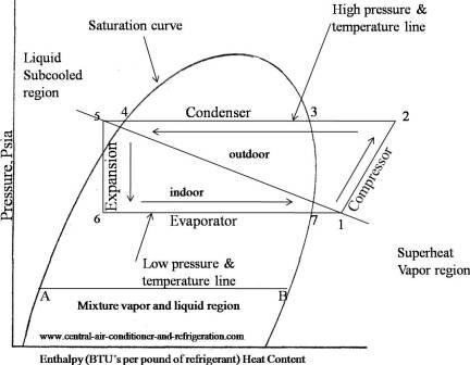 At its heart, the refrigeration cycle has 4 elements that take place
And now to play out a real world example...... (AC, Ill use the output refrigeration temps and the pressures you listed way back in post 465 then show what an ideal refrigeration cycle would look like from that) Tevapout = 64.2°F = 291K Tcondout= 85.6°F = 302K Pcond = 210psig = 1549kPa(absolute) Pevap = 40psig = 377.1kPa(absolute)  AC, as you can see your temperature out of the compressor was actually lower then the one I have on the diagram following a line of adiabatic compression, this is due to the loss of heat to the compressor and thus reducing the amount of effective work done on the system. That's enough for tonight, I'll try to go into how all this can play into sizing of heat pump components tomorrow if i have some time. Last edited by Blauhung; 04-25-11 at 03:46 AM.. |
|
|
|
 |
| Tags |
| air conditioner, diy, gshp, heat pump, homemade |
|
|


 Linear Mode

