 |
|
|
#51 |
|
Apprentice EcoRenovator
Join Date: Feb 2011
Location: Driftless Region, North America, Earth, Solar System, Orion Arm, Milky Way Galaxy,Virgo Supercluster
Posts: 116
Thanks: 13
Thanked 35 Times in 25 Posts
|
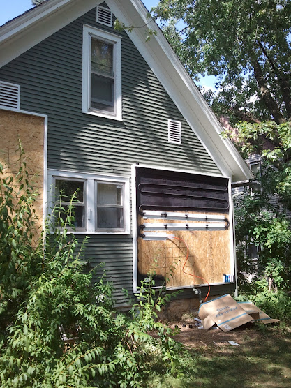
Yeah pretty much. I used maybe 9 screws per OSB sheet. The house has wood siding so it was easy.
|
|
|

|
|
|
#52 | |
|
Helper EcoRenovator
Join Date: Jul 2011
Location: Far northern FLorida
Posts: 43
Thanks: 0
Thanked 9 Times in 7 Posts
|
Quote:
On my Pex Collector, ive got it currently tilted way back at about a 30 degree angle from horizontal and here in Northwest Florida when the outside temp. is at 95 f. in full sun ... at 4 pm. im getting a healthy 175 f and thats just using a 300' roll of 3/4" Pex-B coiled tubing laying in a 3' square wooden box with single pane glass . At first i was concerned i might be approaching boiling temps but alas it became more manageable. |
|
|
|

|
|
|
#53 |
|
Helper EcoRenovator
Join Date: Mar 2011
Location: Sarnia, Ontario, Canada
Posts: 91
Thanks: 8
Thanked 2 Times in 2 Posts
|
Bringing back an old thread, here, but, are there anymore pics? How's it been going?
__________________
TomS |
|
|

|
|
|
#54 |
|
Apprentice EcoRenovator
Join Date: Feb 2011
Location: Driftless Region, North America, Earth, Solar System, Orion Arm, Milky Way Galaxy,Virgo Supercluster
Posts: 116
Thanks: 13
Thanked 35 Times in 25 Posts
|
Sorry I've been really bad about keeping the thread updated, but the project is completed and is up and running. Pics to follow.
|
|
|

|
|
|
#55 |
|
Apprentice EcoRenovator
Join Date: Feb 2011
Location: Driftless Region, North America, Earth, Solar System, Orion Arm, Milky Way Galaxy,Virgo Supercluster
Posts: 116
Thanks: 13
Thanked 35 Times in 25 Posts
|
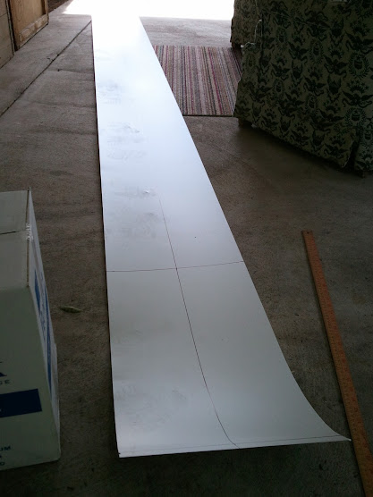
The next phase was plumbing inside the collectors, which meant the fabrication of the heat absorbers. Using rolls of Aluminum flashing as the raw material, I cut and bent it into absorber plates to fit over the pex. I also cut thinner strips of the Aluminum for underneath the pex. The thinner strips acted to increasing the surface area of heat transfer into the pex and also provided a convenient guide for laying the drainback serpentine pattern as I went along.
 AL roll, and marking cuts for top absorbers.  AL piece ready to be bent in my former device (scrap wood form, 5/8" steel bar and a big ol' mallet)  How it fits together.  Apply brute force!  You can see my construction processes; Starting with the back absorber strip as a guide, then straightening the pex over it. Next, applying plenty of Silicone caulk between the two absorber pieces as well as the pex. Everything was nailed onto the plywood with brads because heavy duty staples wouldn't go through the Aluminum. |
|
|

|
|
|
#56 |
|
Master EcoRenovator
Join Date: Aug 2012
Location: Toronto
Posts: 958
Thanks: 40
Thanked 158 Times in 150 Posts
|
One other thing to think about is to make sure your PEX rolls off like wire because it has a memory and should not twist. I am concerned about how the tubing will interact with the end of the aluminum when constantly expanding and contracting. It may cut over time.
|
|
|

|
| The Following User Says Thank You to Mikesolar For This Useful Post: | menaus2 (11-03-12) |
|
|
#57 | |
|
Apprentice EcoRenovator
Join Date: Feb 2011
Location: Driftless Region, North America, Earth, Solar System, Orion Arm, Milky Way Galaxy,Virgo Supercluster
Posts: 116
Thanks: 13
Thanked 35 Times in 25 Posts
|
Quote:
|
|
|
|

|
|
|
#58 |
|
Apprentice EcoRenovator
Join Date: Feb 2011
Location: Driftless Region, North America, Earth, Solar System, Orion Arm, Milky Way Galaxy,Virgo Supercluster
Posts: 116
Thanks: 13
Thanked 35 Times in 25 Posts
|
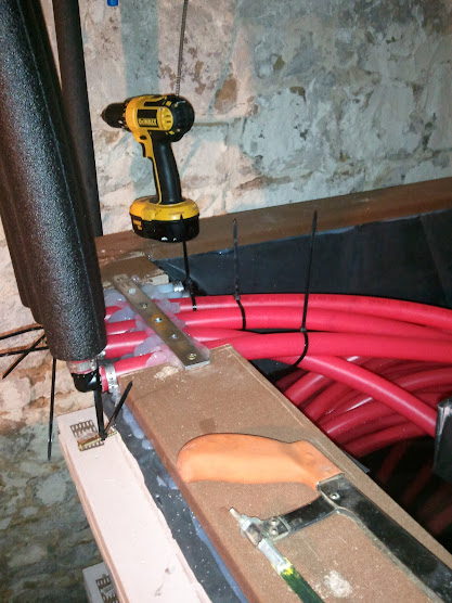
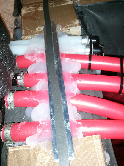
 Progress being made on the right collector.  The 2 heat exchanger loops (one for each water heater) being secured to the tank. Zip ties, a mending plate and a generous dose of silicone kept the unruly 1" pex under control.  Another angle. To the left of the 4 heat exchanger pipes are the two inlets for the collector (just 2 black T's at this stage). The collector inlets pull from the bottom of the tank from the pumps outside the tank up to the top of the collector. You can also see the weatherstripping foam on top of the composite decking, this will create a nice seal for the lid later on.  Another shot of everything. |
|
|

|
|
|
#59 |
|
Apprentice EcoRenovator
Join Date: Feb 2011
Location: Driftless Region, North America, Earth, Solar System, Orion Arm, Milky Way Galaxy,Virgo Supercluster
Posts: 116
Thanks: 13
Thanked 35 Times in 25 Posts
|
 This blurry picture shows my one of the Grundfos pumps being plumbed into to the "U" arrangement.  Both pumps being plumbed into the 2 existing T's that pull from the bottom of the tank.  Attaching a mending plate to the tank lid. There is a sheet of plywood underneath the XPS that the plate is screwed into. The mending plate will be later have a theaded rod through it from the tank edge to secure the lid down.  The two return lines being installed into the lid. They only go past the bottom of the lid a couple inches, so they are far above water line. This ensures air can enter the line during drainback. |
|
|

|
|
|
#60 |
|
Apprentice EcoRenovator
Join Date: Feb 2011
Location: Driftless Region, North America, Earth, Solar System, Orion Arm, Milky Way Galaxy,Virgo Supercluster
Posts: 116
Thanks: 13
Thanked 35 Times in 25 Posts
|
 Drainback pipes through the lid.  A lot going on in the picture. First, the Right collector drainback is now fully attached (the sloped orange pex pipe). Second, to the left of the 4 insulated heat exchanger pipes you can see two pipes with garden hose spigots attached. These are for priming the "U" the pumps are in as well as filling the tank when necessary. Finally, you can see a threaded hook attached to the mending plate attached to the tank lid, this assembly is what secures the lid in place. White blur on the right side of the photo, maybe ghosts are interested in solar energy?  Another shot of the pump plumbing. Starting to look cleaner with insulation and hanging strap securing everything to the tank.  Right collector with absorbing area completed and painted. Starting to attach the corrugated polycarbonate glazing. Look closely and you will see black 2x4 support blocks underneath the glazing. I went this route instead of pole-type support across the whole collector. It seemed simpler and would help contain costs. |
|
|

|
 |
| Tags |
| drainback, water heater, water tank |
|
|