
|
 12-24-10, 11:03 PM
|
#51 |
|
Helper EcoRenovator
Join Date: Dec 2010
Location: Jamaica
Posts: 59
Thanks: 0
Thanked 0 Times in 0 Posts
|
so you think if i replace the 5k pot with the 2k pot, it suppose to solve the problem?
Last edited by fabieville; 12-24-10 at 11:19 PM.. |

|

|
|
12-24-10, 11:31 PM
|
#52 |
|
Lex Parsimoniae

Join Date: Feb 2009
Location: Woburn, MA
Posts: 4,918
Thanks: 114
Thanked 250 Times in 230 Posts
|
What is the actual problem? If you turn the pot up and down, does the output change?
If it does not change, go to the next step. Check the output side and change the chip if needed. Be sure you have your grounds and power supplied to the chip.. |
|
|
|
|
12-25-10, 09:17 PM
|
#53 |
|
Helper EcoRenovator
Join Date: Dec 2010
Location: Jamaica
Posts: 59
Thanks: 0
Thanked 0 Times in 0 Posts
|
I was wondering if you could redraw the circuit to accommodate the 5k pot resistor that i have instead of the 2k pot? Or you can just tell me what resistor values i have to change/add to get it functioning properly like the 2k pot for me please, cause I am sure that it must be the 5k pot that i have now thats causing me not to get the fet to switch on/off. I have even change the fet and the IC and I am not getting the last part of the test to go as stated that when you adjust the pot to one side you should get the 15v zener to read less than 1V.
|
|
|
|
|
12-26-10, 09:22 AM
|
#54 |
|
Lex Parsimoniae
Join Date: Feb 2009
Location: Woburn, MA
Posts: 4,918
Thanks: 114
Thanked 250 Times in 230 Posts
|
 If you are using the original mini-miser pump diagram, it seems like you could just bypass the 3K3 (3.3K) under the trimpot and end up with the same overall resistance. (install a jumper across the 3.3K) But, I think I've ready said, since the voltage on pin 2 (of the IC) is able to go above and below the ref voltage on pin 3 (of the IC). That part of the circuit is working. Since it's already working, why waste more time with it? Why not just move on to the output side and try to find out why it's not changing? Maybe something is wired wrong? Maybe the chip is bad? Anyways, when I refer to a pin number, I'm referring to the LM311N chip.. (Since there is nothing else on the diagram with pin numbers).. Cheers, Rich |
|
|
|
|
12-26-10, 09:39 AM
|
#55 |
|
Helper EcoRenovator
Join Date: Dec 2010
Location: Jamaica
Posts: 59
Thanks: 0
Thanked 0 Times in 0 Posts
|
i was thinking that like how i have the 5k pot install in the circuit i would drop both the top and bottom 3.3k to 0.3k that would take off 3k of each and let the 5k pot equal to having the resistance equalling to a 2k pot. would i be correct?
And to clarify again i have already check the wiring about 10 times now and even change both the fet and the ic and the problem is still the same so i am figuring that it must be because of the resistance of the 5k pot thats y i am asking what i have stated in this message if its possible???? Last edited by fabieville; 12-26-10 at 09:56 AM.. |
|
|
|
|
12-26-10, 10:58 AM
|
#56 |
|
Lex Parsimoniae
Join Date: Feb 2009
Location: Woburn, MA
Posts: 4,918
Thanks: 114
Thanked 250 Times in 230 Posts
|
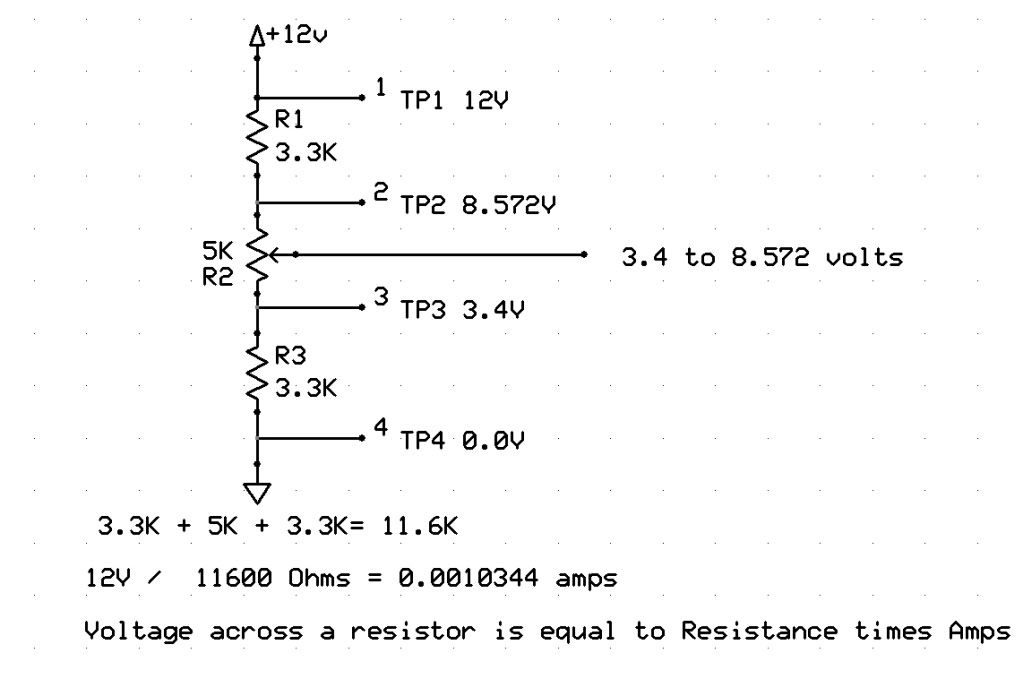 I didn't know what your PV voltage was, so if need to, Google Ohm's Law and re-do the calculations. Or, if you are using 24v PV, you can just double the voltages.. Using 24V PV would put the centertap at 6.8 to 17.144 volts.. Well out of the range of your 5.1v Zener reference voltage. |
|
|
|
|
12-26-10, 01:17 PM
|
#57 |
|
Helper EcoRenovator
Join Date: Dec 2010
Location: Jamaica
Posts: 59
Thanks: 0
Thanked 0 Times in 0 Posts
|
my pv voltage is VOC 21V, rated voltage is 16.8V and rated current is about 6.8amp.
So there you go. You can do the calculations for me now. |
|
|
|
|
12-26-10, 02:29 PM
|
#58 |
|
Lex Parsimoniae
Join Date: Feb 2009
Location: Woburn, MA
Posts: 4,918
Thanks: 114
Thanked 250 Times in 230 Posts
|
Too busy now.. We've got a blizzard coming in.. Got to prepare for it!
Use this calibrator.. Voltage Divider Calculator - RapidTables.com |
|
|
|
|
12-27-10, 09:27 PM
|
#59 |
|
Helper EcoRenovator
Join Date: Dec 2010
Location: Jamaica
Posts: 59
Thanks: 0
Thanked 0 Times in 0 Posts
|
I got the circuit to work now. I bridge the #1 and #4 foot on the IC as shown in the schematic but forgot to connect them to grounds also. So its working now but please can you tell me how to calibrate it? I need to set a operating point but I am unsure as to how to do it. I have a 12V PV panel.
|
|
|
|
|
12-27-10, 11:06 PM
|
#60 |
|
Lex Parsimoniae
Join Date: Feb 2009
Location: Woburn, MA
Posts: 4,918
Thanks: 114
Thanked 250 Times in 230 Posts
|
Hahaha.. Every time I looked at the circuit, I wondered if you had forgotten that ground. I must be physic!
If you don't have an Amp meter, you could try connecting the panel to a light bulb and adjusting the pot for maximum brightness. Mark that posistion on the pot. Then, use some cardboard to block part of your panel(s), so the power output will be lower, like early in the morning, and find the pot posistion for maximum brightness and mark it. You optimum adjustment will probably between those two points. Your charger/load will be different than a light bulb, so you might need to fine tune the setting for best charge rate.. |
|
|
|
 |
|
|


 Linear Mode

