
 |
|
|
#31 | |
|
Helper EcoRenovator
Join Date: Apr 2009
Posts: 30
Thanks: 0
Thanked 2 Times in 2 Posts
|
Quote:
It doesn't have heat times though, but you should be able to figure that out easily enough once you start test-welding: for 3/4" pipe 30 sec is probably way overkill: keep making welds and adjusting the time by a few seconds until the bead is close to the right size per that website. When you get close, you might go in each direction by a second until you know min and max time (per bead size), then use the middle of that range for the welds that count. (the range will change by a few seconds depending on the weather conditions: temperature of the pipe and if there's a lot of wind). |
|
|
|

|
| The Following User Says Thank You to Hugh Jim Bissel For This Useful Post: | coyotesentado (02-20-11) |
|
|
#32 | ||
|
Helper EcoRenovator
Join Date: Apr 2009
Posts: 30
Thanks: 0
Thanked 2 Times in 2 Posts
|
Caught me while I was typing
 Quote:
But, yes, once the math is right, one big well could be divided into smaller wells: thats why we were able to do 230 wells at 250' down instead of having to do one 57,500' well!  (and have to put 6" pipe down it instead of the 1" we used!) (and have to put 6" pipe down it instead of the 1" we used!)We buried our horizontal piping 4 ft down to keep it out of the effects of surface temperature. From my point of view, I'd much rather spend even twice the time once and do it right, rather than have to repair many times (especially if you consider selling the house in the lifetime of the piping (50-100+ yrs!). If you're running all your wells in series, you shouldn't need many joints at all: a U at the bottom of each well, and then a coupling between the ends of each coil of pipe: its best to leave a loop at the top of each well to accommodate expansion and contraction so you don't need elbows there. Last edited by Hugh Jim Bissel; 04-22-09 at 12:50 PM.. Reason: clarification of my phrasology |
||
|
|

|
|
|
#33 |
|
Supreme EcoRenovator
Join Date: Mar 2009
Location: Portland, OR
Posts: 4,004
Thanks: 303
Thanked 724 Times in 534 Posts
|
Glenn,
Thank you for your interest... > You estimate in the Oregon area that two 200-ft wells would be > required.? I assume, alternatively, four 50-ft wells.? Putting these > in line with a simple header arrangement would allow the wells to > be easily connected together.? Thanks for spotting my error... In western Oregon where I live: 1 Ton (12,000BTU/jhr) = 200 ft borehole (or) 2 each 100 ft boreholes (or) 4 each 50 ft boreholes (etc) %%%%%%%%%%%%%%%%%%%%%%%%%%%%%% [UPDATE: When I first wrote this, I thought it was correct, but experience has shown that the idea needs modification. The deeper you go, the less seasonal temperature fluctuations will affect the temperature of the earth. The opposite is also true, and the shallower, the more seasonal temperature shifts will affect the temperature of the earth. The following picture illustrates this principle: 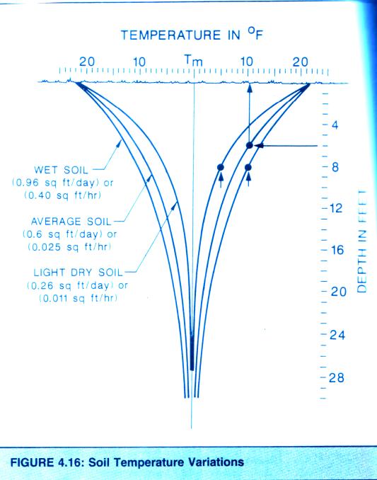 In my case, I ended up drilling 16 holes, with an average depth of 17 feet each. The top of each borehole was 2 feet under the surface of the earth, so the effective depth of each borehole was 15 feet. So my total borehole length was 16 X 15 = 240 feet. But since this was close to the surface of the earth, it was certainly not as effective as a 240 foot deep hole. During the winter of 2010-2011, I ran a very small heat pump 24 hours a day. I was able to extract useful heat but I was not able to log so much useful data. Nonetheless, it is clear to me that the idea works. It is also clear to me that drilling shallow holes, as I did, will require that more holes must be drilled. %%%%%%%%%%%%%%%%%%%%%%%%%%%%%% In the part of Oregon where I live, temperature swings are not as large as they are in many other parts of the country, so the heating and cooling load is generally less than in many other places. The information I have gotten from quite a few local sources is that the rule of thumb, when estimating the amount of borehole required here is 200 ft. of borehole for every Ton (12,000 BTU/hr) of cooling/heating required. Because my house is small and well insulated, my design heat load is somewhat less than 12,000 BTU/hr. I have found that respectful conversation with GSHP installers and water well drillers who also drill wells for GSHP installations (most do), will readily yield this rule-of-thumb information for your particular area. Also, I show how you can experimentally derive this information for your own specific location yourself at this URL: http://ecorenovator.org/forum/introd...nifesto-2.html. The blog posting also cites a document that I took as the source for my test. You would do well to read and understand that document before you do your own test. One aspect of my test that may appear as a source of error is that the test hole I used was only 12 ft. deep. It would likely give you misleading results to only use a 12 ft. test hole in your location. As the source document points out, your test hole should be as close in size and construction detail as the actual boreholes you plan to use. In my case however, I live in a very small house, which I have re-insulated very well, and I live in a relatively mild climate, and most importantly I am actually planning to use many 12 to 15 foot deep boreholes. So in fact, the borehole I used does resemble the boreholes as they will finally be constructed. The rest of your thinking is correct regarding using a branching loop field. > ...where the piping could easily be lifted out and replaced if necessary... Generally, the piping is designed to go in the ground and to stay in the ground. > ...considering adapting my Bobcat (since I have one) to do vertical > drilling to 50-ft.? And, I imagine the adaptation could be done for > less than the $10k price that somebody quoted me)? This sounds great! I wish you the best on this one. Please post photos as this progresses. I guarantee that you will have considerable respect for loop field installers when your own loop field is complete and working! But if you're actually thinking about doing this yourself, you need to give yourself the benefit of all the information you can lay your ambitious hands on. So if you're expecting to save the better part of $10,000 you'd be well advised to spend $100 and go straight to the source of information: Publications | Manuals. In fact, they offer a ground source installer course at a pretty reasonable cost. My advise is to go for it! > I would assume maintenance, in event of leaks, would present no > particular problems with the more conventional methods of > pipe connection.? I think that there's probably a good reason why most states require fusion welding and pressure testing of GSHP loop fields. I'm not saying that you're incorrect, but I'd advise you to do more research. There are also other issues such as being able to achieving flow turbulence and minimizing friction losses, etc. that might not be apparent at this stage of your thinking.  GSHP_guide > ...the rest of the installation...could be handled by most any qualified > HVAC installer.? Am I right?? There's probably less cost and drama in the HVAC portion of the project, but your best bet would be to hire someone with successful experience in GSHP installation. But overall, you have correctly identified that the majority of the cost & work is in the loop-field. But Glenn, if you are going to go to this length, I would advise you to also consider abandoning forced air and going with hydronic radiant floor heating. Not 'staple up', not the panels that go on top of the floor, but what's known as 'wet system' where the PEX is embedded in a 1.5 inch layer of concrete. When properly done, this offers substantial advantages over forced air, as the heat pump is not called on to raise the working fluid (water) to as high a temperature.  hydronic-heating Hope this has answered your questions. Regards, AC_Hacker Last edited by AC_Hacker; 05-19-11 at 07:49 PM.. Reason: CORRECT OVER-SIGHT... |
|
|

|
|
|
#34 |
|
Supreme EcoRenovator
Join Date: Mar 2009
Location: Portland, OR
Posts: 4,004
Thanks: 303
Thanked 724 Times in 534 Posts
|
I'm not sure if this stuff is getting out of sequence or not, but HJB (AKA: Hugh Jim Bissel) shared a great link to information on pipe fusion technique here: (Polypipe - Heat Fusion and Joining Intro). It's the best and clearest info I have seen and I didn't want it to get lost in the shuffle.
Best Regards, -AC_Hacker Last edited by AC_Hacker; 01-02-11 at 03:45 AM.. |
|
|

|
|
|
#35 |
|
Supreme EcoRenovator
Join Date: Mar 2009
Location: Portland, OR
Posts: 4,004
Thanks: 303
Thanked 724 Times in 534 Posts
|
(* Interesting post from another group *)
> From: "Paul Phillips" <cptrdbrd@yahoo.com> > To: wastewatts@yahoogroups.com > > Hi all > I have been tossing around the geothermal idea for a some years > and I am getting closer to starting work. wile doing some research > on well drilling, I came across "driven well" this is where you use a > special made point that threads on the end of galvanized pipe and > you drive it into the ground up to 100-150 ft. they usually have slots > or holes to let water into the pipe at the bottom. > My thought is not to have the holes in the bottom. all so then you > made a manifold on the top to allow you to make a sort of tube in tube > heat exchanger, you could run say 3/4" pex with 1/4" of closed cell foam > down the middle. this would give you a closed loop design. if you could > do multiples of this like a spider design to 50-100" you may not have to > drill expensive wells. > > Paul Paul, I have a portion of a manual called "Drilling Methods for shallow geothermal installations", that was written by a Swedish Geology Prof named Olof Anderson, date unknown. From studies conducted in the early 1980's, they cite rammed (AKA: driven) co-axial (AKA: tube-in-tube) steel tubes as one of the possible methods for GSHP installation. Corrosion seems to be a problem. Regular steel has a mass loss of 2.15% per year and is estimated to be good for 32 years, copper has a mass loss of 1.74% per year with an estimated life of 40 years. Stainless steel appears to have negligible mass loss and is expensive. * please see attached scans * 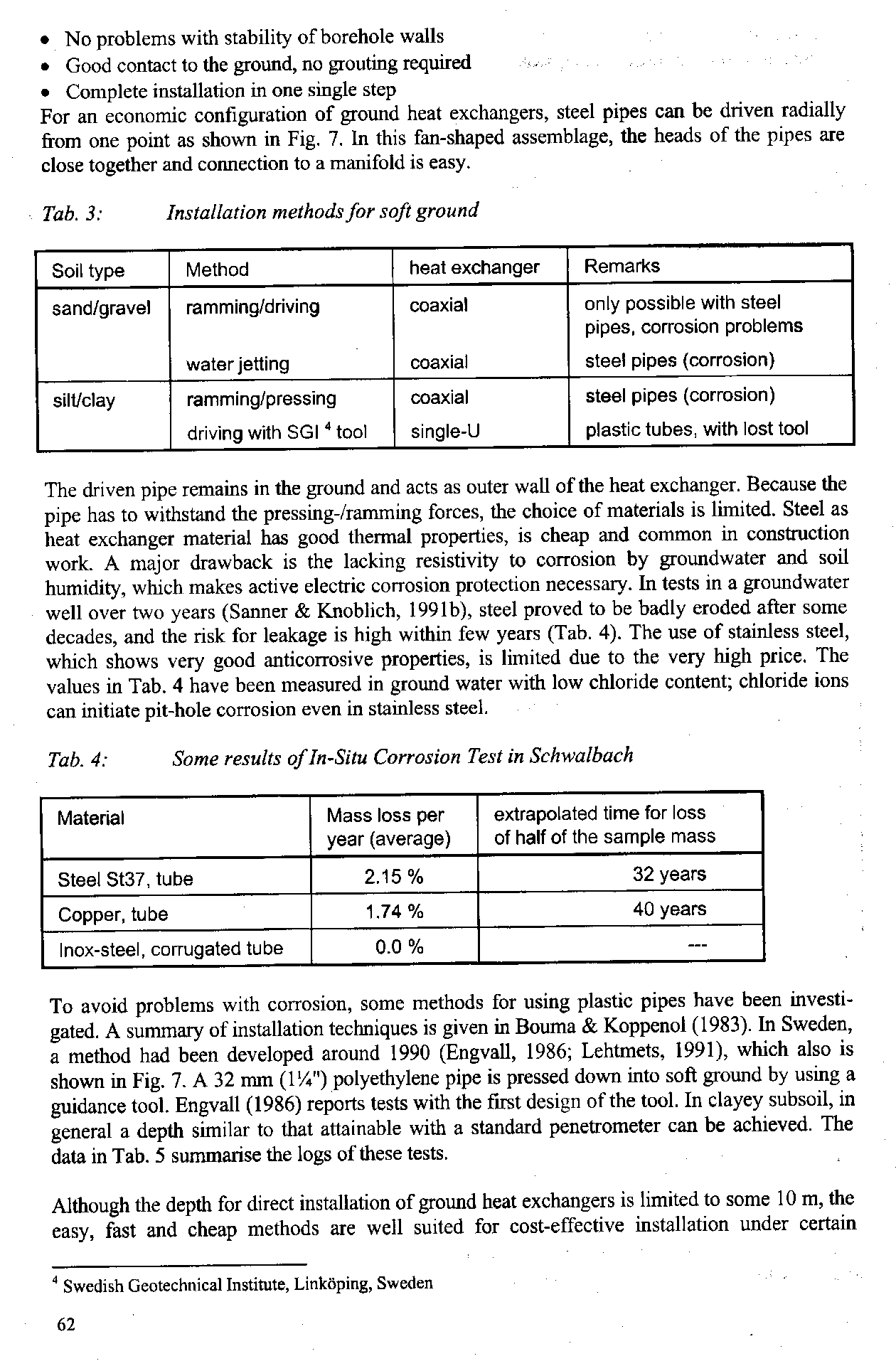 Regards, -AC_Hacker Last edited by AC_Hacker; 05-27-09 at 10:39 PM.. Reason: in-line images, fix upside-down image... |
|
|

|
|
|
#36 |
|
Supreme EcoRenovator
Join Date: Mar 2009
Location: Portland, OR
Posts: 4,004
Thanks: 303
Thanked 724 Times in 534 Posts
|
Before we open up our Air Conditioner, it would be a good idea to consider how the thing works, so that we will have some appreciation for the stuff we're going to be looking at and in some cases modifying.
EDIT: 1-28-2012 It is useful to get info from several sources. Here in an excellent explanation of how refrigeration works from a seasoned HVAC guy, originally posted here. END OF EDIT: 1-28-2012 I have talked to lots of people, modern people, who just can't understand why I think I can use a refrigeration compressor (actually Air Conditioner compressor), which they associate with cold, and to bury pipes in the ground, which they also associate with cold, and reasonably expect that this procedure will result in making my house warm. I've tried to use refrigerators as an example, which they associate with cold, to explain the process, and I usually get to see people with pitying eyes stare at me, wondering how an otherwise reasonable person could be so misled. But I'll try again here... First off, what is heat? We have an intuitive notion that heat is what we feel when we touch something that is warmer than our hand. And the opposite, cold is what we feel when we touch something that is less warm than our hand. If we look really deeply into the question of what heat is, we will find out that heat is actually a manifestation of energetic movement of molecules. The greater the movement, the greater the heat. But something what might feel cold to us, like cold water, in fact has this energetic molecular movement that results in heat. It may have less energetic movement than warm water, but it still has energetic movement. In fact, any material will have this energetic movement that we will call heat until the very cold temperature of −459.67°F. SO compared to that the temperature of the ground is pretty warm. Let's look at this refrigeration diagram: 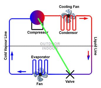 This is a simplified diagram of the components in the refrigeration cycle of our air conditioner. I have taken the liberty of adding the light green line to the diagram from the compressor across to the "valve" (AKA: metering device, expansion valve, capillary tubing, etc.). This green line marks the boundary between the high pressure side (AKA: high side, pressure side, hot side) which is on the right side of our diagram, and the low pressure side (AKA: low side, suction side, cold side) which is on the left side of our diagram. This whole refrigerant circuit is hermetically sealed from atmospheric pressure, it is in it's own special refrigeration world, there's no water in there, there's no dirt in there, just refrigerant and some lubricant. Before we power up the compressor, the pressure of the refrigerant gas/liquid on both sides of the diagram is under greater than atmospheric pressure (probably in the range of 50 to 100 psi), but it is equalized on both sides. Neither side is hotter or colder than the other. When we put power to the unit, we intentionally create an imbalance and we exploit the changes that result from this imbalance. There may be a bit of a time delay, but very soon, the compressor starts working and it begins discharging refrigerant gasses out of the compressor and sending them through the high-pressure side tubing. They travel through this tubing until they get to the "valve" where their progress is slowed almost to a standstill. But the compressor continues pumping away and the gasses back up and the pressure increases and so does the heat of the gases and at some point, the gasses are under so much pressure that they almost begin to turn into a liquid, a hot liquid. This hot, highly pressurized gas then flows through an assembly which allows for the removal of some of the heat. This assembly is called the condenser. When enough heat is removed, the hot gasses in the condenser actually do turn into liquid, and in so doing they yield up an accellerated amount of heat. (* This gives us a thermal imbalance that we can exploit to make our heat pump. This thermal imbalance is where the heat that we desire to heat our house or our water is extracted. But where does it come from? Read on...) The hot liquid then moves along to the expansion valve. The expansion valve in small air conditioners usually takes the form of what is known as a 'capillary tube', or 'cap tube' in the trade. This cap tube uses the friction created by both a very small diameter, and a relatively long length to consistently restrain the flow of liquid refrigerant in the circuit. The cap tube is reliable, fairly consistent and cheap. The cap-tube is designed to work with our compressor, so we'll want to salvage it when we begin major surgery. Loook at the second picture: 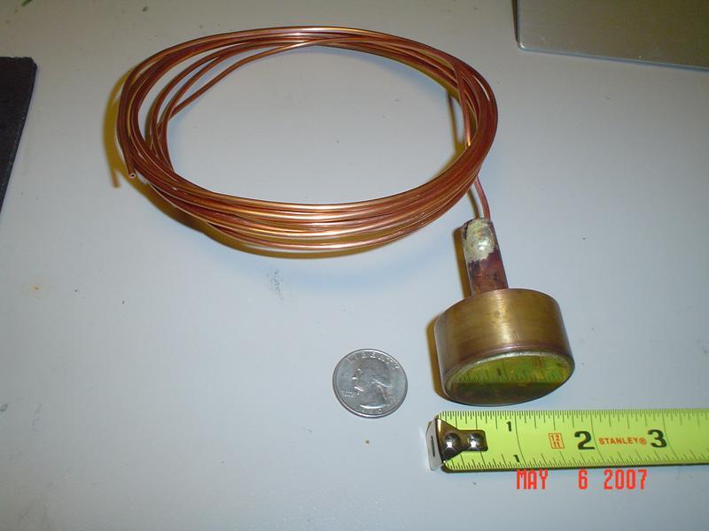 cap-tube.jpg So the liquid flows in a restrained manner through the cap tube, which may be 4 to 8 leet in length, all coiled up, inside our air conditioner. Then something strange and wonderful happens... While the compressor has been feverishly creating a high-pressure condition on the right side of our diagram, it has also been feverishly creating a low-pressure condition on the other side of the diagram. As the refrigerant travels through the cap tube, at some point very near the exit of the cap tube (less than an inch) it enters the low pressure created by the compressor. When this liquid enters the low pressure area, the imbalance of pressures force the liquid to instantly flash into vapor. (* This instantaneous flashing into vapor causes an instantaneous drop of temperature. Here we have another thermal imbalance which we will also exploit in our heat pump. This extraordinary imbalance, cold in this case creates a thermal "vacuum" into which heat from surrounding earth or water will flow. *) Look at the third picture: 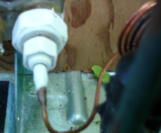 frost formation I'm also posting another diagram of a refrigeration circuit. It's really a great illustration, and you should be able now to understand just what's going on in this picture. 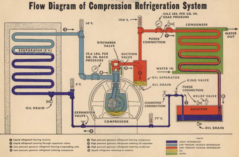 refrigeration-illustration & & & & & & & & & & & & & & & & & & As an addition, here are some documents that also introduce the principles of refrigeration:
And here is a clear, plain-english description of the refrigeration process. And here is an information packed index page leading on to amazing projects by people determined to wring extra performance out of their computers by using refrigeration technology to cool down over-clocked CPUs. Best Regards, -AC_Hacker Last edited by AC_Hacker; 01-28-12 at 01:12 PM.. Reason: in-line images |
|
|

|
|
|
#37 | |
|
Supreme EcoRenovator
Join Date: Mar 2009
Location: Portland, OR
Posts: 4,004
Thanks: 303
Thanked 724 Times in 534 Posts
|
OK, sorry to take so long... life is a multi-threaded process.
So now we're going to open up the case, but we are not yet going to open up the refrigerant system. Safety first, make sure you have the Unit unplugged. Locate the plug before you start using the screw-driver. 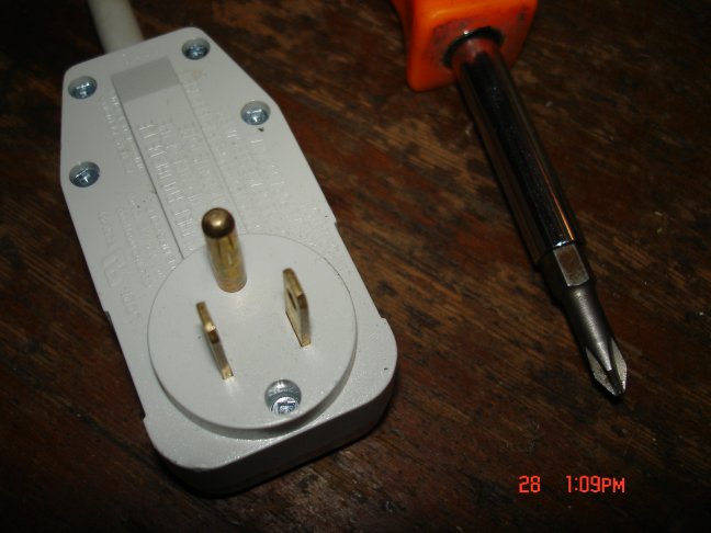 unplugged (NOTE: when I take something apart anymore, I keep my digi-camera close at hand and take photos at every step. This way if I forget exactly how it goes back together, I can refer to my photos.) Most AC units are built very much alike. If you have a different model, even a different brand, you should be able to follow right along with the text & photos here. SAFETY NOTE FROM bma1984: Quote:
Here's what I ended up with:  naked-AC-unit.jpg one of the first things we should look for is the schematic. It will be on a piece of paper stuck inside, or glued to a panel in side, but they all have them and they have useful information. 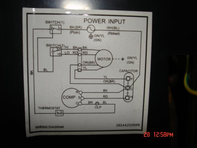 schematic A couple of things to note in the schematic... On my schematic, in the lower central area of this schematic, coming off of the BR wire of the compressor, there's a symbol labeled "OLP". This indicates the Over-Load Protector, and is a round bi-metallic module that is under the plastic cover on top of the compressor. It serves the purpose of preventing the compressor from overheating. If a maximum temperature threshold is reached, a bi-metallic spring will interrupt the flow of current to the compressor. We'll look at it later. Also of interest is the "capacitor". symbol on the lower right of the schematic. The compressor and fan motor each use a starting capacitor to nudge them into starting. In most of the air conditioners I have seen, there is only one capacitor case, with two capacitors inside, a smaller one for the fan and a larger one for the compressor. If we decide that we don't want to use the fan, we can still use the same capacitor, and just ignore the fan side. Next is the compressor, it's the main reason I bought this AC unit. It accounts for most of the weight and cost of any air conditioner. 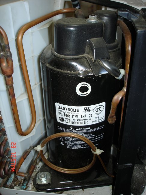 compressor-side There are two copper tubes that come from the compressor. One comes out of the top. This is the high pressure discharge from the compressor. the other tube usually goes in the side, near the bottom of the compressor. This is the low pressure (AKA: suction side) tube. We can expect that the high pressure side will become warm when the compressor is running, we can also expect that the low pressure side will be cooler to the touch, when running. On the side of my compressor is a number in large-size type that reads, "qa075cde". If I Google that number (qa075cde - Google Search) , I eventually find out that my compressor is made by LG and that it is between 1/3 and 1/2hp with a displacement of about 7.5cc/rev. Most room a/c's use r22 which usually means it has mineral oil or alkybenzene. (* I also find out that there are several hacker forums where people more knowledgeable than I am, are re-purposing AC units for all sorts of things. *) While I am looking around the compressor, I also see a coil of thin copper tubing. This is called the "cap tube", short for capillary tube, which is the air conditioner's refrigerant metering device. 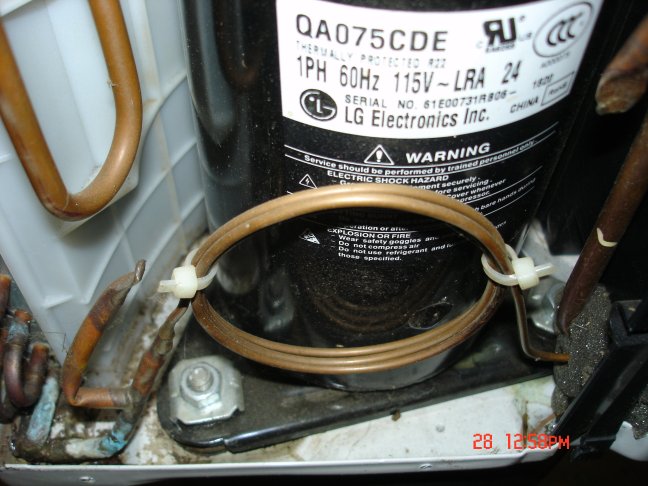 cap-tube Also of interest, but perhaps a little hard to see, is that the compressor is sitting loosely on little rubber vibration absorbers. These are also matched to the compressor, so if possible I will keep them too. This blog software will not let me select more pictures in one 'reply', so I will continue this section over into another 'reply'. (* ...to be continued... *) Regards, -AC_Hacker Last edited by AC_Hacker; 09-04-09 at 06:47 PM.. Reason: add more text, fix spelling, replace "thermostat" with "OLP" |
|
|
|

|
| The Following User Says Thank You to AC_Hacker For This Useful Post: | vann (06-11-13) |
|
|
#38 |
|
Supreme EcoRenovator
Join Date: Mar 2009
Location: Portland, OR
Posts: 4,004
Thanks: 303
Thanked 724 Times in 534 Posts
|
Let's take a look at the top of the compressor...
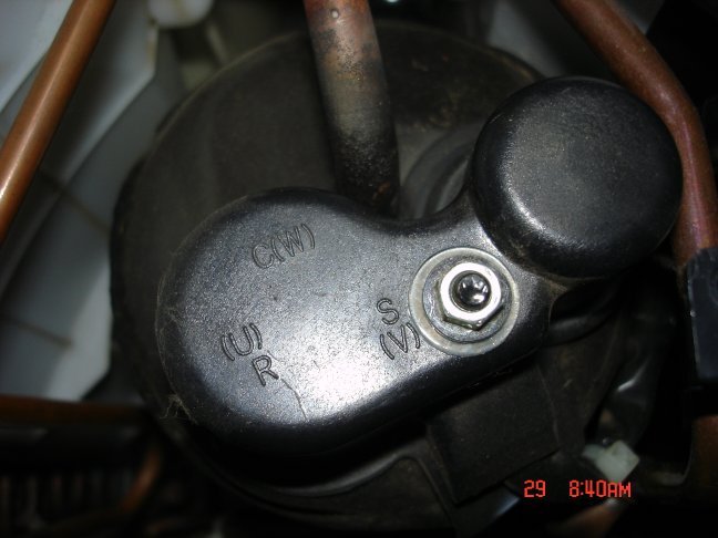 compressor-capped There's a plastic cap, held in place by a single nut. the power wires and the OLP (over load protector) are under this. Take a moment to notice the letters printed at the edge of the cap, we'll see them again. If the AC unit is unplugged, let's remove the nut for a quick look inside. 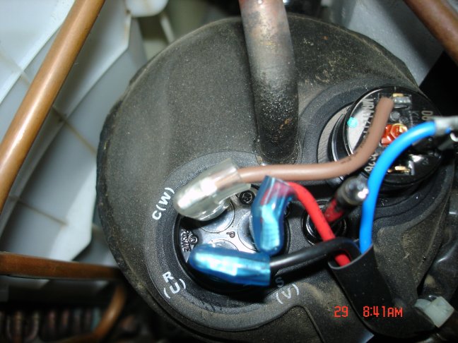 compressor-uncapped Here we see various colored wires that power the compressor. We also see the OLP device which will press against the top of the compressor, when the cap & nut are in place. If we compare what we are looking at to the schemetic, we will see this... 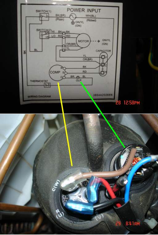 schematic_&_compressor I've drawn in a light green line between the OLP on the schematic and the actual OLP device. I have also drawn in a yellow line between schematic's compressor connections and the real thing. Take a few moments to familiarize yourself with the connections, the wire colors, the letter symbols on the schematic and the letter symbols on the actual compressor. Do they all agree? Now put the cap and the little washer and the nut back on the compressor. The nut should be snug but not really tight. Next, let's look at the rear side of the AC unit. This is the side that will be outside the window. On a day when the AC is running, this radiator will be exhausting the hot air from the room (and the heat generated by the compressor). The name of this radiator (AKA: air-to-air heat exchanger) is the 'condenser coil'. I have drawn a light-blue circle to indicate and area where the aluminum fins got 'mooshed'. If I want to use this condenser, I can straighten out the fins by hand. Small combs are available to help with this job. If the air is not able to flow freely past this part of the condenser, it can't dump it's heat. 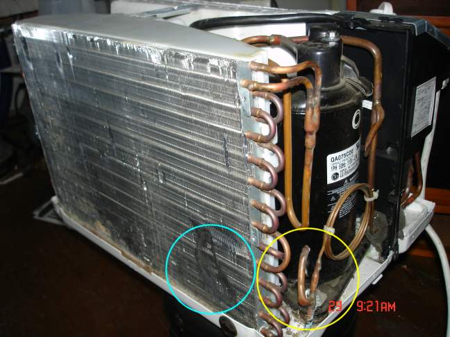 Condenser I have also drawn in a yellow circle around another detail... This piece of bent-over tubing is where the refrigerant was put into the unit at the factory. If this looks a bit funky, it's because in mass production, every effort is made to shave cost from the millions of units that are produced. If a real service valve was here, the price to make this AC unit would be about a dollar more. When millions of units are produced, it adds up to real money. If I decide to build a heat pumpout of this unit, I will need to put in a real service valve (AKA: Schrader Valve) here, and I will put in another one on the 'low-side' of the compressor. 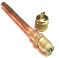 Schrader valve THe Schrader valve comes in various configurations, the most common has the same thread as a 1/4 inch flare fitting, and the valve core is an automobile valve-stem core. be sure that when you braze on a Shrader valve, that you first remove the valve core before you apply heat, and wait until the brazed area is cool to the touch to re-install the valve core, else the valve core seals will melt, stink and fail to ever work again, as I found out. I have reached the end of my picture quota, so... (* to be continued *) Last edited by AC_Hacker; 06-07-09 at 01:56 PM.. |
|
|

|
| The Following User Says Thank You to AC_Hacker For This Useful Post: | vann (06-11-13) |
|
|
#39 |
|
Supreme EcoRenovator
Join Date: Mar 2009
Location: Portland, OR
Posts: 4,004
Thanks: 303
Thanked 724 Times in 534 Posts
|
Lets take a closer look at the flow of refrigerant...
 compressor-to-condenser ...here we see the discharge tube coming from the top of the compressor and down through a 'U-shaped' tube, then splitting into two paths and entering into the condenser coil. I have drawn the directional arrow in RED to indicate that the refrigerant is hot at this point, both because it has been compressed, and because it has picked up heat from the compressor. The U-shaped tube is there partly to help spread out the vibrational stress over a longer distance, to prevent pre-mature failure of the copper tube. The splitting of the refrigerant paths is to raise the efficiency of the condenser coil to expose more high-pressure gas to more air-cooled copper tubing. At the bottom of the condenser coil, the two refrigerant paths converge into one path and enter the cap tube. I have drawn the directional arrow in MAGENTA to indicate that the trip through the condenser has removed heat from the refrigerant. Then the refrigerant flows through the cap-tube and then enters the 'suction side' (AKA: low-side) of the refrigeration cycle.  cap-tube-to-evaporator I have shown the path of the refrigerant through the cap-tube in MAGENTA. I have drawn the circle and arrow in BLUE because this is the point of expansion of the refrigerant, this is where the refrigerant flashes from warmish liquid to very cold gas. When we run the AC unit, we can expect to find frost forming at this point first, and then spread along the tube tward the evaporator tube. here's another detail of the tubing near the condenser: 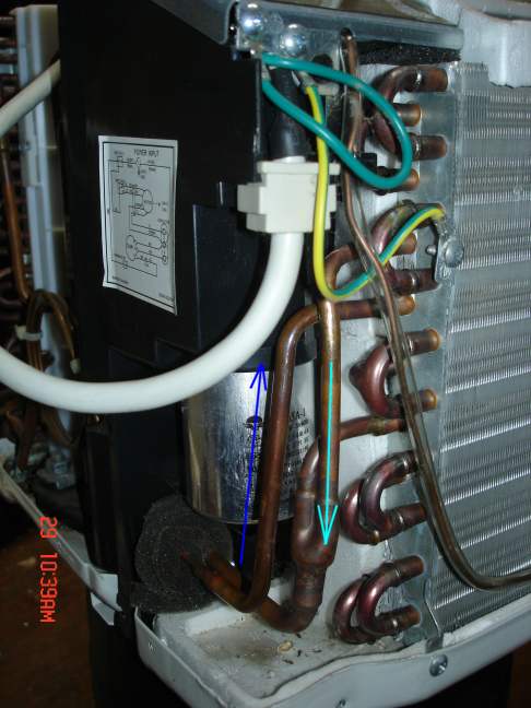 to_&_from-condenser I have drawn the flow arrow to the condenser in BLUE to indicate that it is really cold, and the flow arrow from the condenser in LIGHT BLUE to indicate that some of the cold has been lost, actually heat has been gained. Also note in the background of this picture, the silver cylinder. This is the starting cap for both the fan and the compressor. Next is a full shot of the condenser. 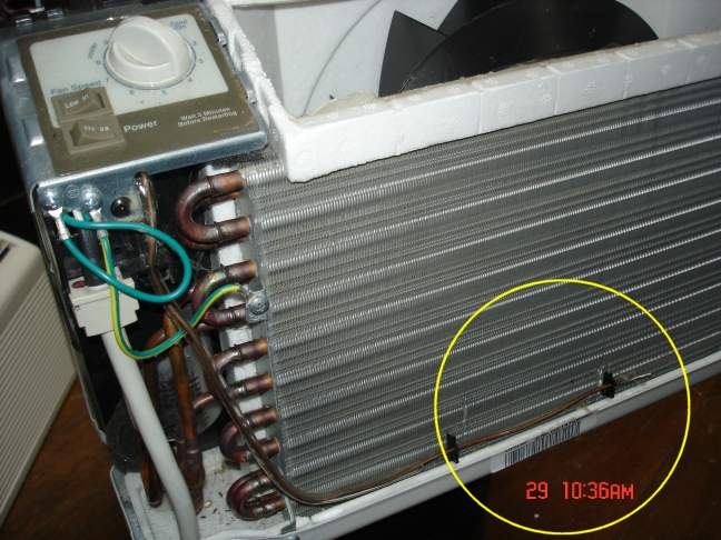 condenser_&_temp-sensor Note the temperature sensor at the bottom of the evaporator coil. It is there to sense the temperature of the exiting room-air and also to sense if the evaporator gets really frosty. It will shut down the AC unit to allow the frost to melt. Then after a few minutes (about 5 minutes) the unit will start up again. If we are clever, we might be able to reuse this sensor for our newly re-purposed machine. Next photo is looking down next to the top of the compressor and shows the return of the refrigerant to the compressor.  back-to-the-compressor The refrigerant has lost some of it's cold to (gained some heat from) the room air during it's trip through the evaporator coil, but after it passes through the filter (which also contains desiccant to remove any water that may have been inside at the time of manufacture), and enters the compressor, it is definitely cooler than the compressor. The designers count on this to help keep the compressor cool. (* to be continued *) Last edited by AC_Hacker; 06-07-09 at 04:31 PM.. |
|
|

|
| The Following User Says Thank You to AC_Hacker For This Useful Post: | vann (06-11-13) |
|
|
#40 |
|
Supreme EcoRenovator
Join Date: Mar 2009
Location: Portland, OR
Posts: 4,004
Thanks: 303
Thanked 724 Times in 534 Posts
|
Let's take advantage of the fact that the cover is off and watch what the unit does under power...
Make sure that the cover is back on the compressor, and that no screwdrivers or wrenches are in or on the AC unit. If you have a watt-meter, this might be a useful time to measure the power consumption of the unit. I let mine run for a couple of hours and here's what it looks like.  watts vs minutes If we look at the evaporator end of the cap-tube, we should see frost forming.  early-frost After it has run awhile, the compressor's heat begins to build and we see that the frost on the evaporator line has decreases a bit. 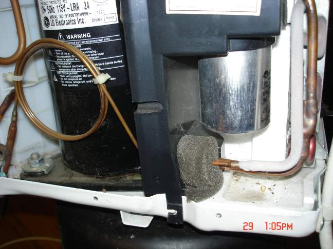 later-frost.jpg I have included here an interesting chart that shows various refrigerants, and when they were discovered.  Refrigerants There's more to learn about the innards of an AC unit, but this should do it for now. This is the conclusion of "We look under the hood to see what's going on". I hope this has been useful for you, and has not only given you a bit of knowledge but has fortified your gumption to continue on with some interesting and useful AC hacking. Best Regards, -AC_Hacker (* Next post: What Can We Do With This Thing? *) Last edited by AC_Hacker; 06-07-09 at 04:38 PM.. Reason: In-Line Images |
|
|

|
| The Following 3 Users Say Thank You to AC_Hacker For This Useful Post: |
 |
| Tags |
| air conditioner, diy, gshp, heat pump, homemade |
|
|