 |
|
|
#21 |
|
Lex Parsimoniae
Join Date: Feb 2009
Location: Woburn, MA
Posts: 4,918
Thanks: 114
Thanked 250 Times in 230 Posts
|
Got some chill testing done. I found the 4-Way valve default in T-Run mode is heating.
After seeing some high power use in heating, I decided to disconnect the 4-way valve, and do my testing today in chill-out mode. Note: The 4-Way valve is marked 230vac. I should be able to control the heat/cool mode for defrosting, with a 240vac SSR. Cooling seemed to work pretty good with the small charge (~26 oz) of R410a, but the pressure surprised me. It was down at 40 PSI ! Is that -7 deg F?? No wonder the copper got frosty so fast! During chill mode testing, the garage temp was 80F, the line voltage was 238 vac. Current would slowly climb and become steady at 5.4A (1.3kw). 39-40 PSI at the service port took the 1/4" test loop down to 24F in just a few minutes. http://ww2.justanswer.com/uploads/pe...a_pt_chart.JPG I tried little Heating mode at the end, but the high pressure scared me. It shot up to 450 PSI real fast, and looked like it was going to creep up to 500. 450 PSI indicates about 126 degs F, but I didn't leave it running because I had the low pressure gauge side connected and didn't have any water in the test loop bucket.. I did not do any long run times and kept an eye on the compressors heat, using the IR temp pistol.. I'm worried about running on such a small amount of R410A. Last edited by Xringer; 09-26-11 at 04:25 PM.. |
|
|

|
|
|
#22 |
|
Lex Parsimoniae
Join Date: Feb 2009
Location: Woburn, MA
Posts: 4,918
Thanks: 114
Thanked 250 Times in 230 Posts
|
|
|
|

|
|
|
#23 |
|
Lex Parsimoniae
Join Date: Feb 2009
Location: Woburn, MA
Posts: 4,918
Thanks: 114
Thanked 250 Times in 230 Posts
|
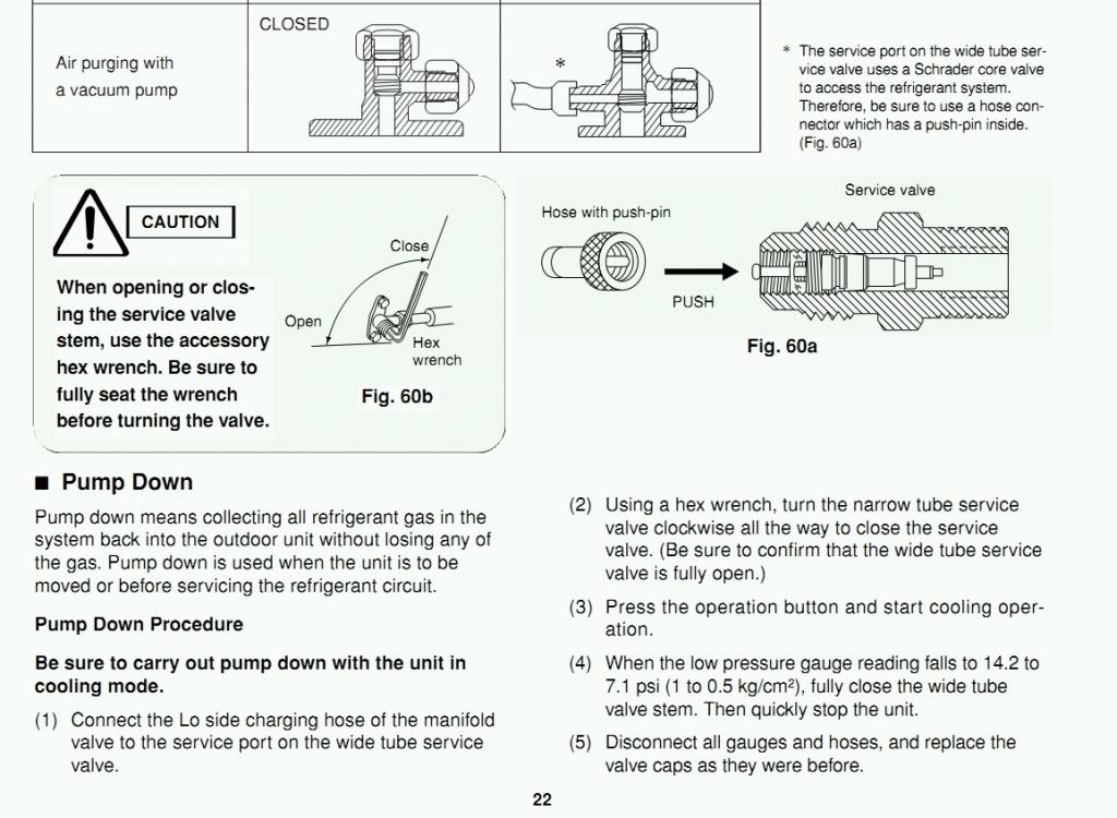
At the end of today's testing, I decided to try the Sanyo Pump-Down trick..
 So, I shut off the small Liquid tube valve, hit the toggle switch and watched the pressure drop as the R410A in the little test loop was sucked inside. When the gauge neared 10 PSI, I started closing the large Suction line valve. It was open a full 4 turns! By the time I got it closed, the pressure was going negative! I quickly hit the switch and removed the manifold hose.. It didn't hiss at all.. When I removed the cut-off from the Schrader service port, no hiss.. I think the little test line-set might have a little vacuum in it!! I'll put the vacuum pump on and vac the loop down good, before I start the system up again.. I'm thinking that 40 PSI is a sign that I need to get some R410A. My HVAC guy told me not to buy anymore of these little 28oz cans.. He said I should get a regular installer sized tank of R410A. I just might take his advise, since this repaired unit is looking better and better for going back into service..  eBay -prices |
|
|

|
|
|
#24 |
|
Lex Parsimoniae
Join Date: Feb 2009
Location: Woburn, MA
Posts: 4,918
Thanks: 114
Thanked 250 Times in 230 Posts
|
If anyone is having a problem seeing that video? If you can't watch it, please PM me..
Thanks, Rich PS: More R410A is in the mail...  http://www.ebay.com/itm/R410a-R410-R...-/330486995097 Last edited by Xringer; 09-28-11 at 09:12 PM.. Reason: Ebayed? |
|
|

|
|
|
#25 |
|
Lex Parsimoniae
Join Date: Feb 2009
Location: Woburn, MA
Posts: 4,918
Thanks: 114
Thanked 250 Times in 230 Posts
|
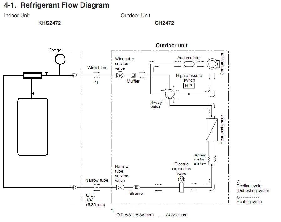
The Pump Down function works great. It saves all the R410A back inside the unit.
So, the line-set can be disconnected for work on the system. (or moving it).  The gauge set would be where the vacuum pump connected.  In Pump-Down, closing the Narrow Tube Service Valve, (in cooling mode) allows the compressor to pump all of the R410A into outdoor HX coil. Trapping it. Now, I've started wondering about completely removing R410A from the system. The Idea: The "Indoor Unit" HX would be replaced with a Gravity Trap. It would consist of a 'T' connector installed in a short loop (that replaces the line-set). The bottom of the 'T' would point downwards into a connected tank, the feed lines would be configured in a 'V' shape, to enhance gravity flow. (Lines and tank would start off in a vacuum of 200 microns). The Pump Out operation might start, by opening the narrow tube (liquid line) service valve. This would pressurize the 'T' and the collection tank. And maybe draw in some of the R410A in it's liquid state. That should depend on the volume of the collection tank. If the tank was pre-chilled, that should enhance collection. Opening both valves, and running the system in cooling mode, should pump liquid R410A into the 'T', where some of it will drop down into the tank. The collection tank should sitting on a scale. (To see if this hack works)! Pressure in the 'T' could be increased by partly closing the Wide Service Tube Valve. Which might drive more liquid into the 'T' and into the tank. Gas from the Wide valve would enter the compressor and help drive the liquid into the storage tank. When the scale showed the total charge had been collected, a valve on the output side of the 'T' could be closed to reduce the pressure in that side of the recovery T-loop. At <14 PSI, the Wide valve would be closed. Followed by the Narrow valve, and power off. If it worked, they should be only a very small amount of 'gas' still in the system. Comments please. Thanks, Rich Last edited by Xringer; 09-29-11 at 10:02 AM.. |
|
|

|
|
|
#26 |
|
Supreme EcoRenovator
Join Date: Mar 2009
Location: Portland, OR
Posts: 4,004
Thanks: 303
Thanked 724 Times in 534 Posts
|
I haven't been following your entire collection of threads on this project, so I'm not sure what you are wanting to accomplish with your unit today.
(* refigerant recovery just might warrant it's own thread *) However, here is a post from a over-clocker phase change forum regarding refrigerant recovery. Unfortunately the pics are missing, they would have been very helpful. If you were relentless, you might be able to find the original post with the pics on archive.org. DIY Refrigerant Recovery Machine! [Archive] - Overclockers Forums ...and another: how do i build a Refrigerant Recovery Unit [Archive] - XtremeSystems Forums ...here's someone in the trade discussing how it is done: http://www.hvacfun.com/a-all-you-nee...g-recovery.htm ...and of course this classic: How to make homemade Redneck freon reclaimer | Video « Wonder How To ...and then there's this guy: ...lastly this one, which looks promising: http://www.refrigeration-engineer.co...-Recovery-Unit -AC_Hacker
__________________
I'm not an HVAC technician. In fact, I'm barely even a hacker... Last edited by AC_Hacker; 09-29-11 at 11:59 AM.. |
|
|

|
|
|
#27 |
|
Lex Parsimoniae
Join Date: Feb 2009
Location: Woburn, MA
Posts: 4,918
Thanks: 114
Thanked 250 Times in 230 Posts
|
I've seen some of that stuff before and of course watched the RedNeck hack again. (3rd time I think).
 The main goal of removing all the R410A from the system would be to allow the system to be cleaned out, with a flushing agent. This would allow for replacing the POE oil (which might be contaminated) when recharging the unit. I'm running tests on this repaired system, and I'm still a bit worried the compressor might be in danger of being damaged, due to bad (or a lack of) POE oil.. I did like those DIY systems that incorporated oil separators. Since you would not want old oil in your storage tank. If I decide to buy a new indoor unit for this repaired system, It might be best to have a very cleaned up 'charge' in the system, before installing the new indoor unit. |
|
|

|
|
|
#28 |
|
Lex Parsimoniae
Join Date: Feb 2009
Location: Woburn, MA
Posts: 4,918
Thanks: 114
Thanked 250 Times in 230 Posts
|
This afternoon, ran a short chiller test with 1.5 gallons of water in the test loop tray.
About 1" of ice quickly formed around the coil loops, but since there was no water circulation, the over-all water temperature only got down to 67F. Then, I reconnected the 4-way valve and started up some heating tests. Because of the high amperage, each of the three runs was limited to three or four minutes. When current got too high, I shut down the run let it rest for a minute or two before restarting. Due to the ice, I just recorded the temperature on the LCD/sensor on the hot side (large pipe of line-set). (Temperature of the gas going into the cold water). 1. 400 PSI 9A (2,140w) 80 F 2. 460 PSI 9A (2,140w)90 F 3. 500 PSI 10A (2,380w) 100.5 F You will notice that I let the pressure get a little higher on each test. On the last test, I figured that 500 PSI a bit too high for safety. The current and pressure rise showed no sign of slowing down, so testing was terminated before anything popped. http://i46.photobucket.com/albums/f1.../referFlow.jpg http://i46.photobucket.com/albums/f1...CL/outdoor.jpg ~~~ There is a big difference in current use. Heating 10A+, Cooling 5.4A steady. The Sanyo controller was running the system because of the ground on the T-Run test terminal. The controller had no way of knowing that I had unplugged the 4-Way valve during the chiller tests. The default mode is heating (with the 4-way valve energized). Why is the heating (default) mode using twice as much power? Guesses: 1. One or more of the thermistor sensors are providing feedback to the controller, telling it to pour on the power..?. 2. There isn't enough R410A in the system, to run in heat mode properly.?. Plans: Add more R410A (currently in the mail) to the system. And re-test.. It will be interesting to see if the cooling power goes up from 5A, and the heating power drops down a bit, as more R410A is added. Cheers, Rich |
|
|

|
|
|
#29 |
|
Lex Parsimoniae
Join Date: Feb 2009
Location: Woburn, MA
Posts: 4,918
Thanks: 114
Thanked 250 Times in 230 Posts
|
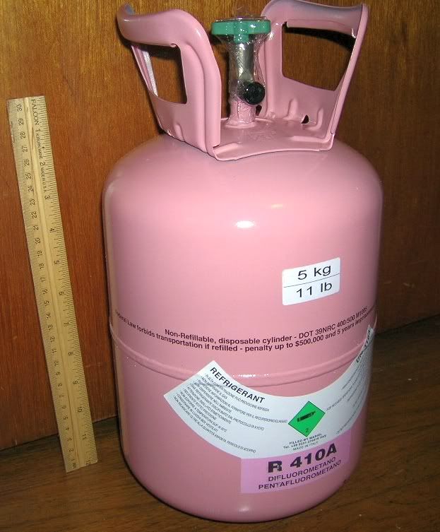
I wonder if my good old HVAC buddy is doing anything this weekend?
The Red Sox aren't going to be on TV, and it's real overcast and rainy today.. Guess what Fedex dropped off!  The penalty for re-using the tank is kinda like motor vehicle homicide. General Laws of Massachusetts Murder defined Just a MUCH larger fine.. |
|
|

|
|
|
#30 |
|
Lex Parsimoniae
Join Date: Feb 2009
Location: Woburn, MA
Posts: 4,918
Thanks: 114
Thanked 250 Times in 230 Posts
|
I suspect this repair is going to hold, and that my little 1/4" test loop is too short to tell me how this unit will operate with a Sanyo indoor unit.
So, for $375.17 (it was $329.23 before shipping & taxes), I decided to buy another indoor unit.  |
|
|

|
 |
|
|