
|
 03-21-11, 04:14 PM
|
#1 |
|
Lex Parsimoniae

Join Date: Feb 2009
Location: Woburn, MA
Posts: 4,918
Thanks: 114
Thanked 250 Times in 230 Posts
|
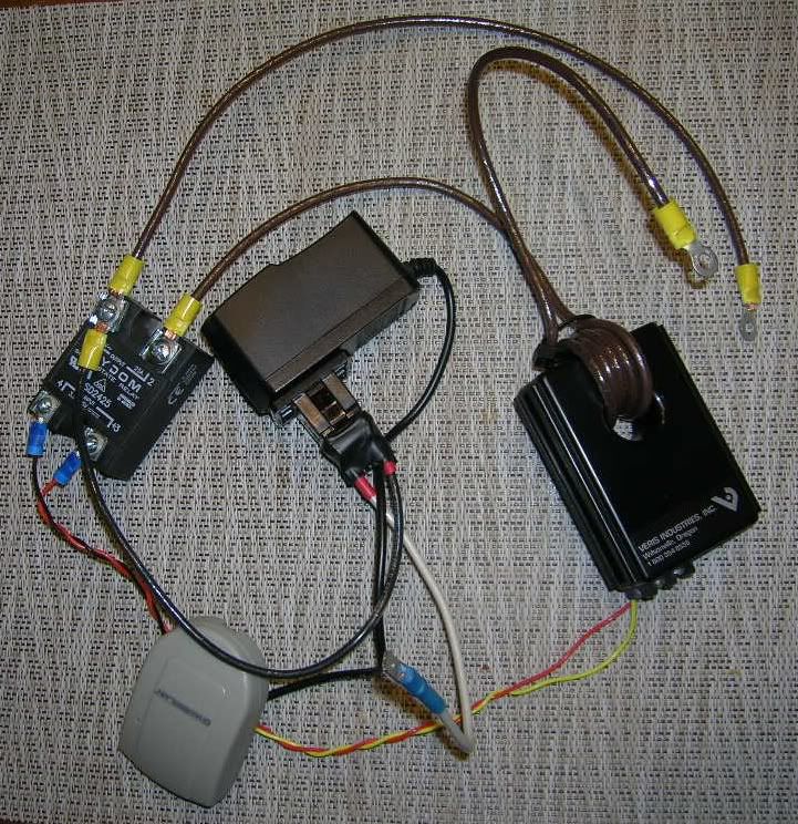
This 230vac adjustable power limiter can be pre-set to turn off AC power
to a load and reset itself within a few hundred milliseconds. 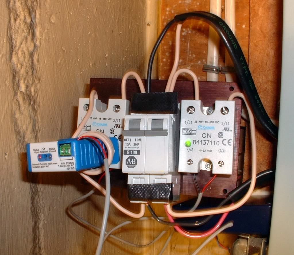 The blue device on the left, is a non-contact current sensor. It's set-point has been set to about 9.5 amps. (~2300 watts). The dark blue box (lower right) contains a transistor switch that sends 5 VDC to the two SSR on each side of the (open) 10A breaker in the middle. (The green LEDs on the SSRs indicate they are on). If the load exceeds 2.3kw, the current sensor closes it's contacts. This grounds out the base of the transistor, shutting it off. That removes the +5v control signal from the SSRs, shutting them down. (The SSRs turn off as the AC voltage crosses Zero volts). ~~~ The Sanyo hiccups!  Once the current stops, the current sensor shuts down. (It gets it's power from the magnetic field of the 230vac line). It's contacts become open. A cap on the base of the transistor charges up and the transistor turns back on. That turns on the SSRs and the Sanyo restarts within a few seconds. (The SSRs turn ON as the AC voltage crosses Zero volts). |

|

|
|
03-21-11, 04:23 PM
|
#2 |
|
Administrator

Join Date: Aug 2008
Location: Germantown, WI
Posts: 5,525
Thanks: 1,162
Thanked 374 Times in 305 Posts
|
Pretty slick little setup.
 What happens when the Sanyo restarts?
__________________
Current project - To view links or images in signatures your post count must be 0 or greater. You currently have 0 posts. To view links or images in signatures your post count must be 0 or greater. You currently have 0 posts. & To view links or images in signatures your post count must be 0 or greater. You currently have 0 posts. |
|
|
|
|
03-21-11, 05:14 PM
|
#3 |
|
Lex Parsimoniae
Join Date: Feb 2009
Location: Woburn, MA
Posts: 4,918
Thanks: 114
Thanked 250 Times in 230 Posts
|
The first test was done with High Power mode on.
Which is always good for a big ramp up in power use. Maybe around 2.6 to 3kw.. When it hit the set-point, it went quite for a second, started right back up, but at normal power levels (460w). Then started the stepping-up sequence again, heading for 3kw, but never getting there. At 2.3kw, it hiccuped again. After three hic-cycles, I took it out of HP mode. Right now, we have a lot of snow and ice on the coil, so I'm waiting to see if we get a defrost cycle. That would be a good test of the unit. If it can get into defrost mode (where it normally uses 1400-1600 watts), I'll be very interested in seeing what happens when the famous After-Defrost-Surge* automatically kicks in. If the auto-breaker's short drop-out can make the Sanyo restart and run up to a more reasonable power level, I'll be happy. If it can't save itself from repeating the defrost power surge after the drop-out, then I'll change the time delay and made the delay a few seconds. That will insure a normal power-up cycle without a crazy surge. ~~~ * After-Defrost-Surge note: My theory is, that some Japanese management guy decided that Americans are so impatient, they will want a big strong blast of heat, within seconds, after the defrost cycle.. So, set motors for ludicrous speed! |
|
|
|
|
03-22-11, 07:45 AM
|
#4 |
|
Lex Parsimoniae
Join Date: Feb 2009
Location: Woburn, MA
Posts: 4,918
Thanks: 114
Thanked 250 Times in 230 Posts
|
It worked!! Read the latest news over at
http://ecorenovator.org/forum/geothe...html#post12588 |
|
|
|
|
04-01-11, 06:06 PM
|
#5 |
|
Lex Parsimoniae
Join Date: Feb 2009
Location: Woburn, MA
Posts: 4,918
Thanks: 114
Thanked 250 Times in 230 Posts
|
In the lower right side of this picture, there is a little blue box..
It contains this little transistor circuit. 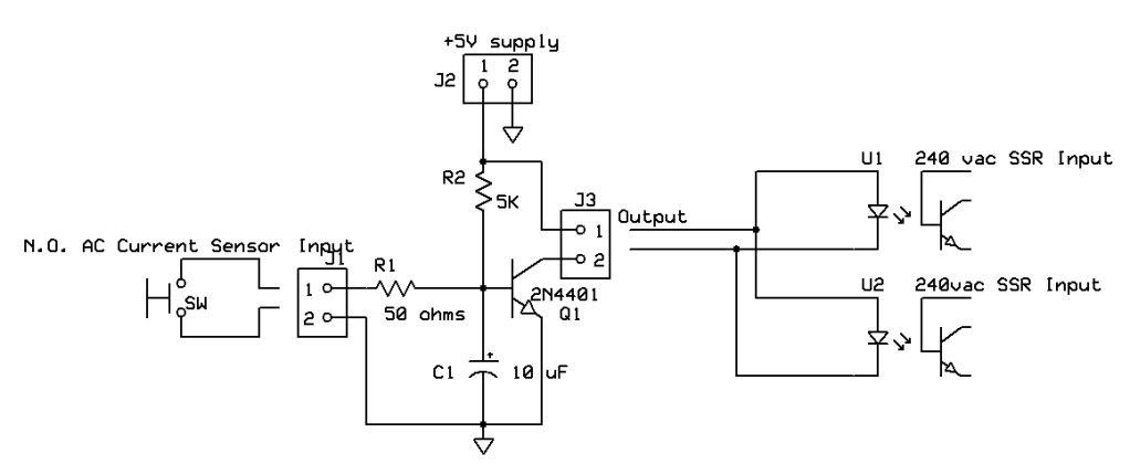 The AC current sensor closes it's contacts at ~9.5A and shorts out the voltage from R2, that's been keeping Q1 turned on. Once Q1 turns off, the SSRs also turn off, causing the Sanyo to Hiccup. ~~~ Last night and this morning, we had a little snow storm. (it's still snowing now)! The wind was blowing the snow around, the temperature was 32F, the Dewpoint was 31F and the humidity was 99%.. Snow and ice was quickly covering up the Sanyo air intake. This AM, we started watching the defrost cycles. Smooth as black ice! This is the way my Sanyo was meant to work! |
|
|
|
| The Following User Says Thank You to Xringer For This Useful Post: | buffalobillpatrick  (05-23-14) (05-23-14) |
|
09-17-11, 11:23 PM
|
#6 |
|
Lex Parsimoniae
Join Date: Feb 2009
Location: Woburn, MA
Posts: 4,918
Thanks: 114
Thanked 250 Times in 230 Posts
|
 Looking at this diagram of the Sanyo Outdoor Unit, I can see how the Power Relay (upper right) could be easily replaced with a 240vac SSR. I would bring in 5VDC from outside to control the SSR, keeping the High Pressure Switch(HPS) and OverLoad Relay (OLR) in series with the 5VDC. It would not be difficult to add a current sensor(@9.5A) with it's control circuit (see above) in series with the OLR & HPS contacts. (The transistor would control the ground side of the 5v power source). Thus eliminating the need for that messy looking relay rig inside the house.. During mild weather, the crankcase heater and other vampire loads could be dropped off the grid, by using a spare X10 to control the indoor 5V power supply. ~~~ It just occurred to me, a second Sanyo Outdoor unit (@9.5A) could possibly be connected to the same outdoor 230vac power disconnect box.. Assuming 20A breakers were installed in mains box. Saving a few bucks for another permit..  |
|
|
|
|
10-03-11, 08:15 PM
|
#7 |
|
Lex Parsimoniae
Join Date: Feb 2009
Location: Woburn, MA
Posts: 4,918
Thanks: 114
Thanked 250 Times in 230 Posts
|
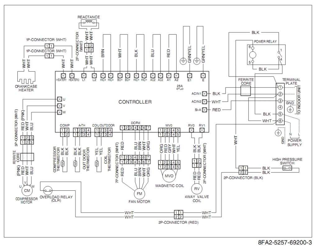
Here's the before pic.
This is going to be the after Hack pic.. [IMG] 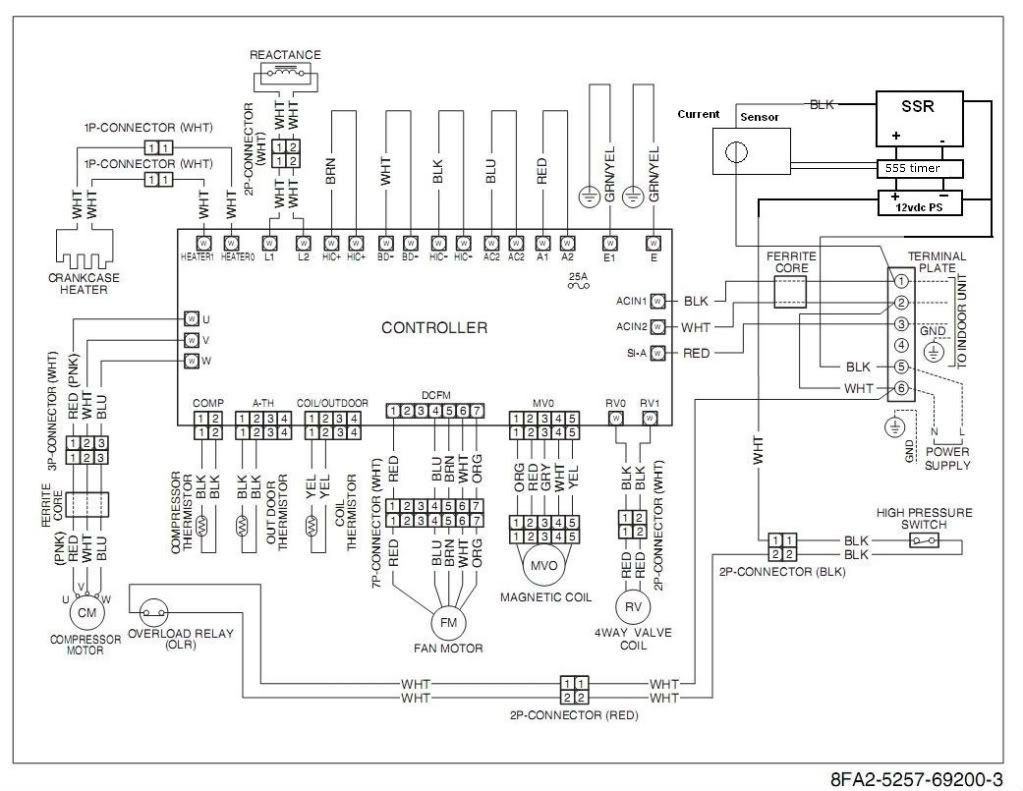 [/IMG] [/IMG]Terminal Plate Connector (5) is the switched side of the 230 supply. The SSR connects (5) to (1), which feeds the indoor unit and the main PCB ACIN1. The Transistor block will be the same as used above. The DC power supply puts out 12VDC with AC inputs from 100 to 240 50/60hz. Current sensor will be pre-set to drop power at 9.5 Amps.. (~2.3 kW). This might void the warranty, so I am considering installing it outside the unit. (As above). One added benefit of using an SSR is no contact spark. Safer if there's any Propane leaking in the area. (BBQ tank on the back deck). ") Last edited by Xringer; 09-05-12 at 01:09 PM.. |
|
|
|
|
10-04-11, 05:52 PM
|
#8 |
|
Lex Parsimoniae
Join Date: Feb 2009
Location: Woburn, MA
Posts: 4,918
Thanks: 114
Thanked 250 Times in 230 Posts
|
 Three Wires: brown wire from the current sense loop goes to (1) brown wire from the SSR goes to (5) White wire with spade lug goes to the WHT wire (high pressure sw etc). This will be installed on the repaired (non-warranty) unit tomorrow. Hopefully, those Ebay parts will do the job.. The Transistor box is from a recycled garage door Open wireless sensor. |
|
|
|
| The Following User Says Thank You to Xringer For This Useful Post: | buffalobillpatrick (05-23-14) |
|
10-05-11, 08:32 PM
|
#9 |
|
Lex Parsimoniae
Join Date: Feb 2009
Location: Woburn, MA
Posts: 4,918
Thanks: 114
Thanked 250 Times in 230 Posts
|
It looked so neat before the hack.. (The compressor compartment is under this plate)
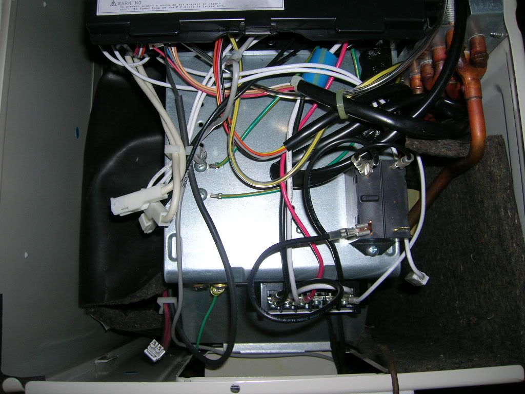 Afterwards, it has a kind of Hacked look.. 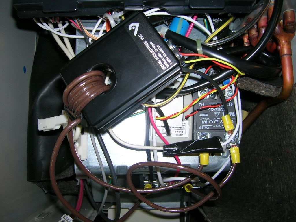 No wires were cut and only one hole was drilled to bolt down the SSR. So, if anything fails, the old relay can be reinstalled in about 5 minutes. The current sensor is set for 10.0 amps and seems to be working perfectly. The system (indoor & outdoor units) should never draw more than 2.4 kW. Once the sensor trips, the indoor unit will reset and start where it left off, before the power outage. |
|
|
|
| The Following User Says Thank You to Xringer For This Useful Post: | RK_Solar_Hopeful (10-30-11) |
|
10-30-11, 09:28 AM
|
#10 |
|
Lurking Renovator
Join Date: Oct 2011
Location: us
Posts: 9
Thanks: 1
Thanked 0 Times in 0 Posts
|
I am gratified that I found your post. It prompted me to join this forum. I am considering the use of SSRs to add more control to my enphase micro inverters. The original thread is on the wind-sun forum under the heading: 10.78kW Enphase system and XW6048 (ForumVB/showthread.php?t=12041)
Thank you for making your information available. I plan to use it!! Rex |
|
|
|
 |
|
|


 Linear Mode

