If you haven't read my posting on the dew point monitor it would be advisable before reading this as it may make more sense...
Part 1 - the hardware
The schematics for all 3 parts of the project are incredibly simple.
There are 3 parts, 2 for the controller and the separate dew point monitor.
1. Main controller
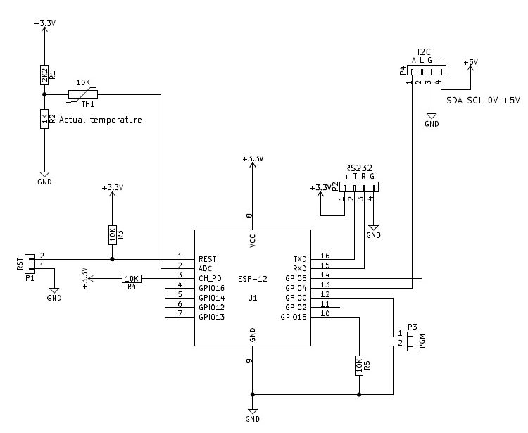
This comprises of little more than a (not shown) 5VDC power supply, 5V to 3V3 power supply (not shown either), an ESP-12 and the resistors needed to make it work and a 10K thermistor connected to the adc input. The I2C bus (2 wires + 5V power) is fed out to the peripherals that are located inside the external unit. The RS232 connection is really only used to program the controller the first time (or if something really screws up!) as any code updates can be done remotely ota (over the air).
2. Peripherals
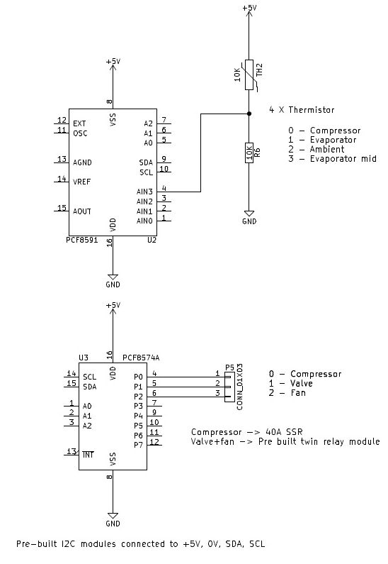
The peripherals comprise 3 x pre-built modules, one to read the temperatures using thermistors and the other a port expander to switch the relays (2 on a pre-built board) on and off. The main relay for the compressor is a 40A solid state relay.
3. Dew point, temperature and humidity monitor

Again ridiculously simple, an ESP-01 connected to a DHT-22 humidity/temperature sensor, a status LED and a button for WPS. Not shown is the 5VDC power supply.
Part 2 - the software
The whole system runs on the Arduino ESP8266 software API and is written in C for the main code and HTML for the web pages.
All the libraries used in the project are open source.
The libraries are:
- Timezone - this allows the clock, which is synchronised from an NTP time server, to display my local time
- ArduinoOTA - This enables ota updates
- ESPAsyncWebServer - this is a much more responsive web server than comes with the standard Arduino ESP implementation
- Ticker - This allows for co-operative multi tasking, i.e. deciding how often a particular code module will be run. There is little point reading tempertures every second, every 30 is more than sufficient whereas updating the clock every second gives a better visual display. This allows control of this.
- Wire - This is for the communication over I2C from the controller to the peripherals.
- EEPROM - Allows reading/writing to the ESP eeprom to store/retrieve operating parameters.
- WiFiUdp - This is used for the UDP clients to communicate with both the NTP time server and the Dew point monitor.
The project also uses the ESP SPI file system (SPIFFS) for storing web pages and stuff required by the web pages.
The code is broken down into modules with discreet functions:
- Read system settings - done once at start up
- Read sensors - every 30 seconds
- Check defrost step and manage defrost cycle (if defrost is running) - every second
- Read dew point sensor - every 60 seconds
- Read and/or refresh time from time server - every second to update time, every hour to synchronise
- Logic to check if a defrost is needed - checks evaporator temperature and if < set defrost point for > defrost delay time, run a defrost cycle
- Set relay states - turns relays on and off as needed
A web server is also running in the background to handle any user input. Updates are sent to the web browser using a protocol called server-sent events. This protocol is handled on Chrome (and others) but not Internet Explorer or Microsoft Edge. The alternative would have been to use AJAX but that would have needed to be initiated from the browser so immediate updates wouldn't have happened. Another possibility that I tried out was web sockets but I kept getting timeouts so ended up abandoning them.
Acuario