Warning, if you are not trained to handle high DC voltages,
please do not attempt any of the experiments discussed below.
The DC voltage from series-configured solar panels can seriously burn and/or kill you.
At work, I've had success using RF coaxial cable as a high voltage DC cable.
Because of the small diameter of the center conductors of coax cables,
the are not suitable for high current applications.
Specs for the cable I've been testing (RG-214U) shows 6 ohms/km in the center conductor,
and 3.1 ohms/km on outer (shielding) conductors.
(RG-8u is more common and has similar specs).
My goal was to test surplus RG-214U cable for currents under 10A,
so the power losses at 100 feet would be minimal. (Around 0.2 to 0.4 ohms).
I'm using a negative ground system. + voltage is on the center pin.
RG-214U is direct burial cable. But beware of using old network cable, underground.
Since some network RG8 type cables have tiny pin-holes in the plastic jacket. Not waterproof.
The aim of these tests is to confirm the utility of the Coax PV power method of power transfer.
If this method is found safe & effective, for use in temporary/emergency installations,
it could be useful to provide power for communications equipment,
using existing (and available) RF coax cables.
~~~
By using panels in series, peak amperage would always remain near the
max amperes rating for a single panel.
So, using four panels in series increases the voltage,
but not the amperage.
Power Loss= Amps squared x Resistance.
For 8A panels, using a 100 run, the losses should be less than 5 or 6 watts.

What worried me is the connections. Crimping and soldering large terminals
at the ends of the cables works okay. But, I wanted to use standard 'N' type coax connectors
(since I also use them for Ham Radio).
Some Type
N connectors are difficult to install, but sometimes,
you can get cables with factory installed connectors..
The center pin of N connectors is tiny. But, I've only had one get blasted.
I think it was installed off-center or it wasn't really gold plated.
The water heater experiment, uses N connectors at both ends (100')
and no heat (losses) can be detected from the connectors.
Typical high power is 600 to 800 watts. With voltages between 60 & 100vdc,
with currents under 8.5 peak amps.
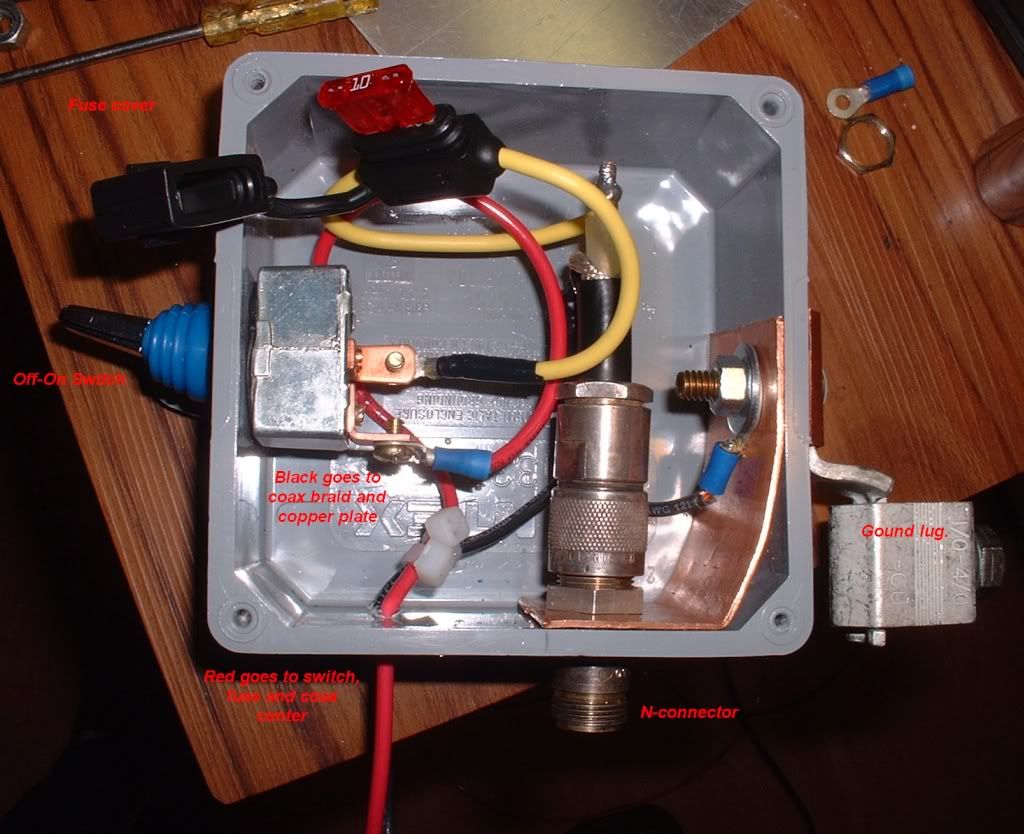
The cable (left) is connected to a N type Bulkhead or chassis connector,
which is wired to the water heater load. (Scan shows 45deg F).
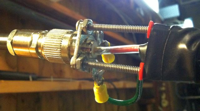
This is the outdoor side. PV comes in the bottom wires.
The + side is switched and fused before going to the center conductor of a very short coax cable..
Which is connected to a double female N bulkhead.
 Warning,
 just like the MC-4 or other Solar panel connectors,
these can NEVER be unplugged or plugged in while the sun is on the panels..
The power will arc weld/melt the center pin. It will have to be replaced.
This flexible cable has an OD is 0.405" and can be quickly buried a few inches underground,
just by parting the sod with a spade blade.
So far, my results have been good. I've also been using this same setup
on my 500W back-up system without any problems.
Of course, since this is a temporary Ham Radio related research project, (I hold an Extra Class FFC license)
")
and can be quickly uninstalled, I'm not worried about meeting code requirements for buried cables etc.
Edit:
I have not yet tested the low-cost version of this method, which will use the PL-259 / SO-239 type connectors.
These are a bit easier to install and have a larger center pin, which might make it less lossy.
I might try these (cheaper) connectors this summer..