Let's take a look at the top of the compressor...
 compressor-capped
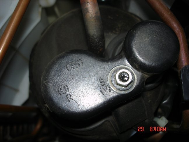
There's a plastic cap, held in place by a single nut. the power wires and the OLP (over load protector) are under this. Take a moment to notice the letters printed at the edge of the cap, we'll see them again. If the AC unit is unplugged, let's remove the nut for a quick look inside.
 compressor-uncapped
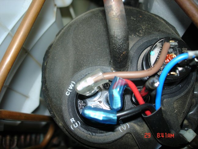
Here we see various colored wires that power the compressor. We also see the OLP device which will press against the top of the compressor, when the cap & nut are in place.
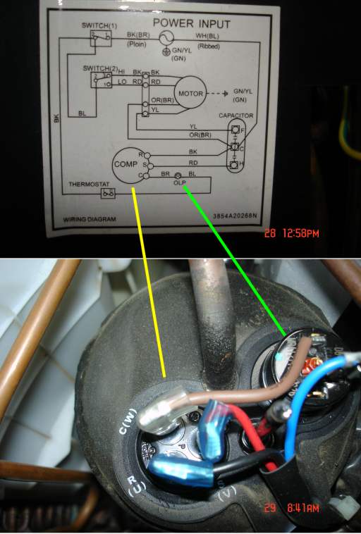
If we compare what we are looking at to the schemetic, we will see this...
 schematic_&_compressor
I've drawn in a light green line between the OLP on the schematic and the actual OLP device.
I have also drawn in a yellow line between schematic's compressor connections and the real thing. Take a few moments to familiarize yourself with the connections, the wire colors, the letter symbols on the schematic and the letter symbols on the actual compressor. Do they all agree?
Now put the cap and the little washer and the nut back on the compressor. The nut should be snug but not really tight.
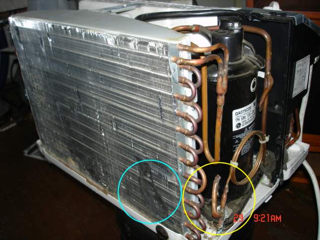
Next, let's look at the rear side of the AC unit. This is the side that will be outside the window. On a day when the AC is running, this radiator will be exhausting the hot air from the room (and the heat generated by the compressor). The name of this radiator (AKA: air-to-air heat exchanger) is the 'condenser coil'.
I have drawn a light-blue circle to indicate and area where the aluminum fins got 'mooshed'. If I want to use this condenser, I can straighten out the fins by hand. Small combs are available to help with this job. If the air is not able to flow freely past this part of the condenser, it can't dump it's heat.
 Condenser
I have also drawn in a yellow circle around another detail... This piece of bent-over tubing is where the refrigerant was put into the unit at the factory. If this looks a bit funky, it's because in mass production, every effort is made to shave cost from the millions of units that are produced. If a real service valve was here, the price to make this AC unit would be about a dollar more. When millions of units are produced, it adds up to real money. If I decide to build a heat pumpout of this unit, I will need to put in a real service valve (AKA: Schrader Valve) here, and I will put in another one on the 'low-side' of the compressor.
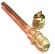 Schrader valve
THe Schrader valve comes in various configurations, the most common has the same thread as a 1/4 inch flare fitting, and the valve core is an automobile valve-stem core. be sure that when you braze on a Shrader valve, that you first remove the valve core before you apply heat, and wait until the brazed area is cool to the touch to re-install the valve core, else the valve core seals will melt, stink and fail to ever work again, as I found out.
I have reached the end of my picture quota, so...
(* to be continued *)