OK, sorry to take so long... life is a multi-threaded process.
So now we're going to open up the case, but we are not yet going to open up the refrigerant system.
Safety first, make sure you have the Unit unplugged. Locate the plug before you start using the screw-driver.
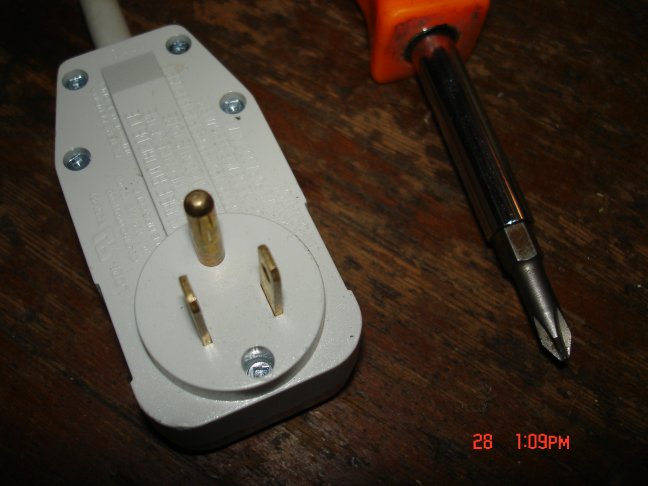 unplugged
(NOTE: when I take something apart anymore, I keep my digi-camera close at hand and take photos at every step. This way if I forget exactly how it goes back together, I can refer to my photos.)
Most AC units are built very much alike. If you have a different model, even a different brand, you should be able to follow right along with the text & photos here.
SAFETY NOTE FROM bma1984:
Quote:
bma1984
I've been ready your forum about diy heat pumps and have learned a tremendous amount. Thank you for your efforts. I had a quick suggestion for page 4 of the forum where you describe the innards of the A/C unit. I'm sure you know, but capacitors of that size can store lethal voltages even when the unit is unplugged. I can tell you are very safety conscious and thought maybe capacitor safety should be mentioned at some point. Thanks again, and hopefully I'll get to offer more useful input in the days to come when I start this project at my house...
Good Luck,
Ben
|
Remove all of the sheet metal screws that look like they might be holding the beast together. When you think you have them all, give the sheet metal & plastic case pieces some gentle tugs to take it off. You might want to re-use all of or maybe part of the case, so treat the sheet metal with care and save the screws all together where you won't lose anything.
Here's what I ended up with:
 naked-AC-unit.jpg
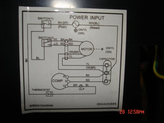
one of the first things we should look for is the schematic. It will be on a piece of paper stuck inside, or glued to a panel in side, but they all have them and they have useful information.
 schematic
A couple of things to note in the schematic... On my schematic, in the lower central area of this schematic, coming off of the BR wire of the compressor, there's a symbol labeled "OLP". This indicates the Over-Load Protector, and is a round bi-metallic module that is under the plastic cover on top of the compressor. It serves the purpose of preventing the compressor from overheating. If a maximum temperature threshold is reached, a bi-metallic
spring will interrupt the flow of current to the compressor. We'll look at it later. Also of interest is the "capacitor". symbol on the lower right of the schematic. The compressor and fan motor each use a starting capacitor to nudge them into starting. In most of the air conditioners I have seen, there is only one capacitor case, with two capacitors inside, a smaller one for the fan and a larger one for the compressor. If we decide that we don't want to use the fan, we can still use the same capacitor, and just ignore the fan side.
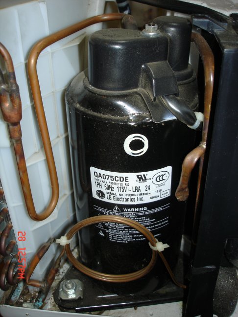
Next is the compressor, it's the main reason I bought this AC unit. It accounts for most of the weight and cost of any air conditioner.
 compressor-side
There are two copper tubes that come from the compressor. One comes out of the top. This is the high pressure discharge from the compressor. the other tube usually goes in the side, near the bottom of the compressor. This is the low pressure (AKA: suction side) tube. We can expect that the high pressure side will become warm when the compressor is running, we can also expect that the low pressure side will be cooler to the touch, when running.
On the side of my compressor is a number in large-size type that reads, "qa075cde". If I Google that number (
qa075cde - Google Search) , I eventually find out that my compressor is made by LG and that it is between 1/3 and 1/2hp with a displacement of about 7.5cc/rev. Most room a/c's use r22 which usually means it has mineral oil or alkybenzene.
(* I also find out that there are several hacker forums where people more knowledgeable than I am, are re-purposing AC units for all sorts of things. *)
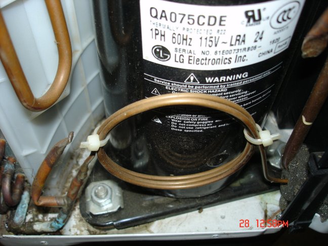
While I am looking around the compressor, I also see a coil of thin copper tubing. This is called the "cap tube", short for capillary tube, which is the air conditioner's refrigerant metering device.
 cap-tube
This cap tube is carefully sized (length and diameter) to the compressor and the refrigerant type. It is possible to size my own cap tube, but if I'm careful, I will be able to use this one. As previously stated, R-22 has characteristics that are very similar to R-290.
Also of interest, but perhaps a little hard to see, is that the compressor is sitting loosely on little rubber vibration absorbers. These are also matched to the compressor, so if possible I will keep them too.
This blog software will not let me select more pictures in one 'reply', so I will continue this section over into another 'reply'.
(* ...to be continued... *)
Regards,
-AC_Hacker