Gary over at
Build It Solar recently got a Thermal Imaging camera and he sent me some photos he took of his
radiant flooring project.
He was interested to actually "see" the effect that 0.018 inch thick plates made to heat radiation patters of a hydronic floor.
Comments
"All the pictures are taken looking down the radiant floor -- there is an about 3/8 thick engineered lumber floor between the camera and the tubes. So, you are seeing the temperatures on top of the laminate floor with the tubes under the laminate."
"The FloorLoopsNS pic #1 is just PEX tube and no heat spreader. The tags on the pictures give temperatures -- so, its 80.2F right over the tube and 75.4F between the tubes."
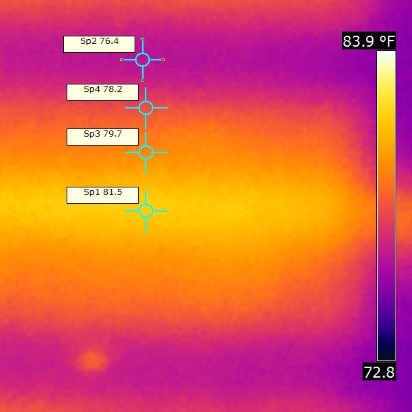
"The other two show areas where I put the spreader plates in. It's clear that the spreader plate does carry the hotter zone out further. These are the 0.018 inch thick plates.
It looks like the area between plates does drop down significantly, but when you compare it to the area well away from the tubes (the 74.6F spot), the plates apparently do help the floor to run a bit hotter even when you get beyond the plate edge."

(photo below is a detail of the effect of the aluminum spreader plate)
Huge 'Thank You' to Gary for getting a Thermal Imaging camera and sharing this information with the DIY community. We all benefit from this.
Best Regards,
-AC_Hacker