Some more photos of the circuit board, and what I am able to identify as important components.

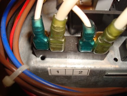
This first photo is the header that is meant for
attaching wires to & from the indoor unit.
Wires coming from the top of the terminal strip go into the circuitry of the PCB on the inside of the unit. Wires from the bottom are for external connections.
The wires connecting to terminals 5 & 6 are 120V 60Hz power for the outdoor unit. Power ground wire attaches to a terminal on the chassis (not shown). I checked for continuity between all terminals and ground and found no continuity on any terminal. I have not yet powered the system to test for voltages.
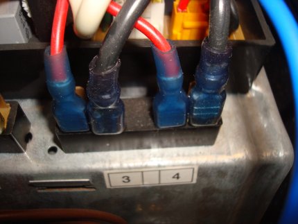
The wires from terminals 1, 2, 3 & 4 go up, into a bundle
and all attach via a single connector at a header on the
PC board as shown above.
I did my best to figure out some of the circuitry.
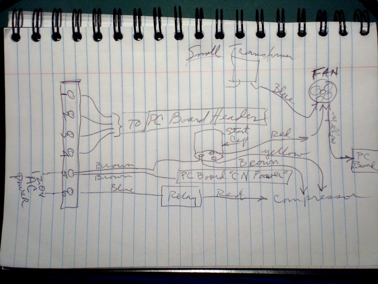
Here is a hasty diagram that I drew of some
of the wiring I could identify.

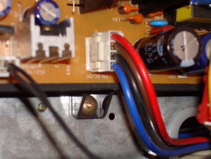
Here is a photo of a relay on the PC board. The blue wire
is coming from the terminal #6 on the header (120V AC in).
The red wire goes directly to the compressor. This is all in
the diagram above.
The next two photos are connections that are NOT on the drawing. Note that these components are NOT on a circuit board and attach directly to the sheet metal frame of the heat pump.
This photo shows what appears to be a SSR that sends power
to the white sump heater wires seen in a previous post.
This photo again shows what appears to be a SSR, but this one sends
power to the reversing valve, which was also shown in a previous post.
Your comments are invited...
Best,
-AC