I re-read that tech sheet about center feeding the Micro-Inverter circuits.
The maximum number of inverters on one string is 16. That means that no matter what, I've always needed at least two strings of inverters.
Center-feeding a string of 16 panels cuts Voltage Rise from 1.92V to .51V, as current has that whole squared thing going for it. Cutting the current in half (by splitting the 16 into two 8s) drops the resistance by 4.
Any kind of a serpentine pattern to try to cut the 24 panels into two sets of 12 panels ends up using a lot of extra (expensive) cables and would likely make the junction box in the middle of the roof, highly inaccessible, under a panel I wouldn't be able to easily remove.
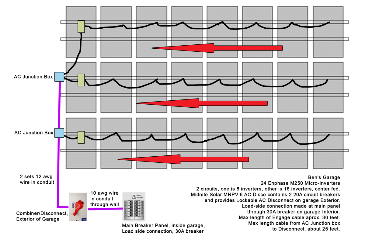
A junction box on the END of a piece of racking, at the end of a row of solar panels makes more sense. Power cables for the micro-inverters would simply run horizontal, one to the next to the next, from east to west. At the west end, the flexible Enphase Engage cable would go into a junction box, where it would then be connected to standard wiring. That wiring would then travel inside conduit on the outside of the building to an AC disconnect box.
Each circuit needs to be protected with a 20A AC fuse. Safety, common sense, and my utility require an AC disconnect. This disconnect needs to be on the outside of the building, properly labeled, obvious to use, and lockable in the OFF position.
One way to do this would be to have an outdoor rated circuit breaker box with two fuses inside. The combined output of that would then go to an outdoor rated 30A AC Disconnect box. From there, the wire would go through the wall of the garage, to the main breaker panel and connect through a 30A circuit breaker.
I looked around to see what was available for equipment to do this. It looks like some off-the-shelf-parts from the Home Improvement Store would work fine. However, I found that MidNite Solar makes a nice little box which puts the work of combining circuits AND disconnecting AC all together in one box. It has a large red lever on the outside. I plan to use the MidNite Solar MNPV6-AC Disco, as I then only need a single box on the outside of the garage.
I'd like to minimize the number of junction boxes on the roof. I would really prefer to not have ANY junction boxes under solar panels. However, I'm also on a corner property, where every car driving past will see the solar panels. So, I want the finished install to look as nice as possible. The main road is on the east side of the property (north-south direction of traffic) so at least anything on the west side of my array should be at least partly hidden.
Also, if I DID have a junction box UNDER a panel, if it was an END panel, I could still get at the box by only un-doing ONE solar panel. I would be able to reach from a tall ladder. Anywhere else would be pretty inaccessible.
I was originally hoping to just have one junction box, as low on the roof as possible, for ease of hookup and accessibility. I'm not sure how well I can have the Engage cable traveling vertically. It means that I need extra "drops" for the additional reach, and there's not really anything to secure the cable to. Horizontally, the cable can be secured to the racking with cable clips and zip ties.
I was thinking that maybe for the top row of panels, I have one extra drop on the cable to reach a junction box at the far left of the middle row of panels. Both cables would enter that box (with waterproof connections on the cable) and join together to the standard 12ga 240V wiring inside and through the conduit.
That would then connect to the junction box on the lower row of solar panels. From there, the conduit (with two circuits worth of 12ga wiring inside) would go around the edge of the roof, and hug next to the building back in the under-hang, follow the corner of the building down, and enter the AC Combiner/Disconnect.
From there, the 10ga wiring would go out the back of the disco, through the wall, and to the main breaker panel, entering through a 30A load-side connection. (Running power IN through a breaker that you might normally expect to see as a branch circuit FROM the main power in the box.)
Of course, that breaker would need to be properly labeled with the correct permanent label stating that it's solar power, fed from somewhere else, may be on even when the main breaker is off, etc.
Anyways, please take a look at this drawing and let me know if you have any thoughts on it. I think it's pretty close to what I want, but if there are improvements, I'm open to them.