Quote:
Originally Posted by Xringer

In the lower right side of this picture, there is a little blue box..
http://i46.photobucket.com/albums/f1...NCL/AB2011.jpg
It contains this little transistor circuit.
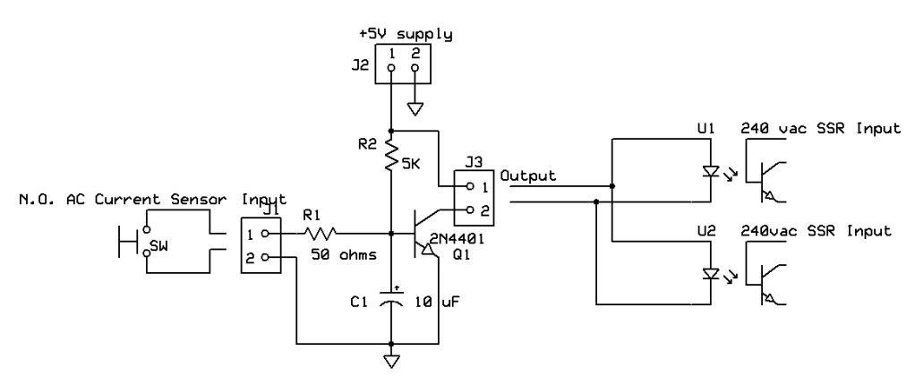
The AC current sensor closes it's contacts at ~9.5A and shorts out the voltage
from R2, that's been keeping Q1 turned on. Once Q1 turns off, the SSRs
also turn off, causing the Sanyo to Hiccup. 
~~~
Last night and this morning, we had a little snow storm. (it's still snowing now)!
The wind was blowing the snow around, the temperature was 32F, the Dewpoint was 31F and the humidity was 99%..
Snow and ice was quickly covering up the Sanyo air intake.
This AM, we started watching the defrost cycles. Smooth as black ice!
This is the way my Sanyo was meant to work!  |
After months of careful deliberations, I've decided to change my design.
I will connect the current sensor to (pin2) trigger the 555 timer.
Over-Current:
The output (Pin 3) of the 555 (connected to the cathode of the SSR dc control) will go high,
turning OFF the SSR for a controlled time period.
I was thinking of selecting C1 & R1 for a 5 minute time delay.


I want to make this change, in case there is a failure in the Sanyo controller,
that causes it not to reset, but to go nuts drawing excessive power..
In that case, a timer would insure there was no relay chatter or
Low frequency 230vac Buzzz! Which, could generate a lot of heat..
Defrost Speed Control:
A 5 minute cooling off period, combined with the 5 minute delay built into the remote,
might slow down a Defrost cycle, but should allow it to be done using less power.
Comments?