The newer generation of units look like this one in the smaller size:
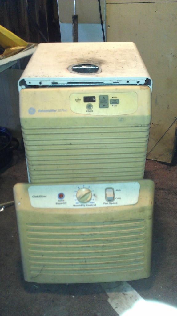
The unit pictured has a front panel from another common model laying on it. The space behind the other panel is where the bucket assembly sits. The units usually have casters and some sort of garden hose fitting you can attach to avoid having to empty the bucket constantly. They don't all look exactly the same close up, but from across a room it is difficult to tell one braand from another.
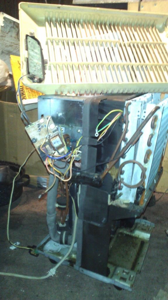
Under the surface, they are almost all the same. The smaller units have a 3000 btu (plus or minus a bit) compressor and single row, finned tube heat exchangers. The tubes are high-density finned, uber thin wall, and rifled on the inside for high heat transfer efficiency and reduced cost.
Due to their ultralight nature, these radiators will spring a leak if you look at them the wrong way! Do not try to separate the fins from the tubes, or the end caps, or bend or twist them, or... you get the point. If you are going to separate the coils and reposition them, do it with the interconnecting tubing, it is much heavier and stronger.
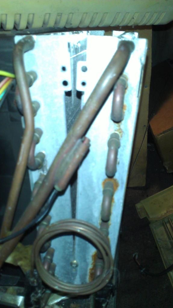
Above the capillary tube lies the defrost thermometer. In the newer units, it is electronic.
The capillary tubes in these units is very long. They limit the BTU throughput and force a very low evaporator temperature. In comparison, here is a replacement tube for a commercial cabinet freezer:

The controls in these newer units are no longer mechanical. They all have a control board of some kind in them and a few sensors to detect temperature and relative humidity. Defrost sensing is done by the control board, and all of them I have seen rely on a thermistor to sense temperature. They also have a humidity sensor which tells the unit how to act.
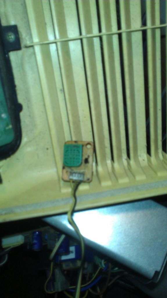
To me, this little sensor looks eerily like one of these (DHT series humidity/temp sensor):

If the unit still works as manufactured, it should be fairly easy to "jinx" the machine by replacing the humidity sensor data with the thermometer data. That way, the built in defrost control would still operate. The DHT sensors are a well trodden road in Arduino territory. Warping the data stream would not be a complicated endeavor. It could be possible to set the unit as normal, only the readout would display the approximate temperature instead of humidity. The unit could then be set as a thermostat.
If the unit doesn't operate correctly, but the relays on the control board and the defrost sensor still do their respective jobs, a new control scheme could be built to repurpose the unit for not much money. This is a perfect job for an arduino or other embedded microcontroller.
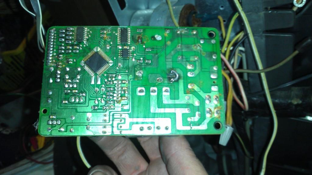
I brought this unit back to life by replacing the "pico-fuse" with a short solder jumper. If the unit draws excessive current, the solder melts just like a fuse. In the above picture, the chip at top center is a buffer between the microprocessor (the diamond) and the relays that control the compressor and fan.
If you look close, you can see four little silver circles on the circuit traces that run between the micro and buffer chip. These are "factory test points" that you can tie directly to an added controller to hijack the compressor and fan. This unit has only three relays: compressor, high fan, low fan. The fourth output has no relay on the board. If desired, one could add another "sugar cube" relay to the vacant spot on the board, and it would switch mains voltage to control another device (such as a heater, reversing valve, or water pump). The buffer chip also has "extra" unused buffer switches that could also be used if desired.
Most of the units have buffer IC's that wire up like this example circuit:

Rather than tying the input pins to a parallel port, we just tie them to digital ouput pins on the Arduino board (or other controller -
SEE HERE)
Raspberry pi owners use these IC's to interface their controllers with relay shields. It seems the r-pi and its 3.3V output pins don't always trigger the relays like they should. Since the shields were originally designed for 5V (TTL) logic, they sometimes ignore the 3.3V logic "high" signals. The ULN chip was found to be the cheapest fix ever.
