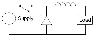
When I looked at this circuit, I assumed it wasn't a voltage step-down. But a voltage booster.

Assuming the Supply is the PV panels, the switch a MOSFET and the load is just a big non-reactive 10 Ohm resistor,
it seems to me there would be AC type voltage applied to the load when the FET is turned off..
So, the circuit is a step down for DC, but maybe it can make a little AC.?.
FET On:
66vdc applied to load, via inductor. Magnetic field builds up, until the load is
drawing about 6.6A. 66v x 6.6a = 435.6watts.
FET OFF:
Magnetic field quickly collapses inwards, generating a pulse of high voltage.
Since the field is moving in the opposite direction, the polarity is reversed.
The diode feeds the negative voltage-current pulse into the bottom of the load.
And the +plus side is fed into the top of the load.
Since the reverse-polarity pulse voltage is much higher than +66v,
it's power is absorbed almost instantly into the 10 Ohm load.
So, my argument is, repeated jolts of reverse-polarity of HV during
the FET-Off time, will heat up the load more, because that voltage
is not limited to 66v (into 10 ohms).
So, on average, over time, the voltage seen by the load is going to be higher than 66v.
(The resistor load doesn't know + from -).
Higher voltage into a load, means it's going to dissipate more power..
Or, maybe at FET On, the XL of the coil is going to slow down the current enough
to mathematically cancel out the large pulse of HV when the field comes down.?.
Making the average voltage even out..?.
Maybe it's time get out the books again..
