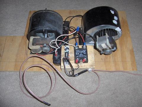
Its been quite some time since I started this series on making a DIY thermal differential controller. I had gotten away from the project, but more recently needed a thermal differential controller for the project you see above. I’m happy to say that I now have a working controller.

So, what has changed? Really, not that much. The main change is that I am now using LM35 temperature sensors instead of thermistors. This not only makes things easier to program, but also they’ll be a bit more accurate. In addition to that, they also cost a bit more. A thermistor is roughly $0.20 and the LM35 is about $1.70 each. Well worth the extra buck fifty each.

For my specific project, I decided to use a solid state relay. I am using 110V AC power, have a few solid state relays handy, and it works great with the Arduino since you can power it directly from the Arduino without using a transistor to provide more power to a normal relay’s coil.

Another component I realized I needed after doing some testing was a small capacitor. The long lead (20ft+) on one of the temperature sensor was susceptible to noise. I put a 10uf capacitor on the signal line and it cleaned up the signal. I’m sure a little bigger or little smaller capacitor would work just fine. The shorter (~5ft) lead didn’t have this problem so I did not add a capacitor to that signal line. If you have two long wire runs to your temperature sensors, a capacitor should be used on both.

Lastly, we need to add a power supply for the Arduino since it can’t run off 110V AC. For this, I used an old cell phone charger which is essentially just a 5V power supply. It runs off 110V AC, so it plugs right in to the wall. It also seems just about everyone has one of these laying around which makes them easy to find, and cheap.


{ 2 comments }
Hey. Don’t know if you are still on this website, forum. But I do have a question about the capacitors. I’m not sure where to put them. Your schematic from Part 4 has 2 capacitors. Somehow they don’t look like they are the ones you have on the long wire probe to get rid of noise. 10 Mf must then mean an electrolytic capacitor. If so the polarity needs to be considered. Is this correct? Parallel or series to the lm35? I’m pretty much a beginner. Built the circuit and the long wire makes temp for that sensor all over the place. Thanks a lot.
I’ve since eliminated the capacitors from the design. I have added software filtering. Take a look at the forum thread for the most up to date info.
http://ecorenovator.org/forum/appliances-gadgets/1503-daoxs-diy-arduino-thermal-differential-controller.html
Comments on this entry are closed.